As touch screens have gradually replaced mechanical buttons in handheld consumer devices, consumers have begun to demand real-time responses due to the lack of tactile response. The user has become accustomed to the mechanical touch of the button input when the button is pressed, as shown in FIG. Recently, the lack of a good tactile feedback design has driven the demand for electronic tactile response systems.
This article refers to the address: http://

Figure 1. Software-based push activation button
The use of piezoelectric drives to achieve tactile feedback is a promising approach that has been used in a few consumer devices for many years. Piezoelectric haptic feedback has many advantages, including: fast response, ultra-thin appearance, low power consumption, and a large number of available piezoelectric materials and assembly processes.
Piezoelectric characteristics and comparison
Piezoelectric materials come in a variety of shapes, sizes, thicknesses, voltage ranges, forces and rated capacitances that can be machined to specific shapes to meet specific application and package requirements, and are available in single and multi-layer configurations. Multiple piezoelectric bodies can achieve strong tactile feedback and a variety of different tactile sensations.
Piezoelectric drive applications that operate at and near the resonance point include:
â—Vibration excitation and elimination
â—Micro pump
â—Micro engraving system
â—Ultrasonic drilling / welding / engraving / anatomy / metering
Applications that work below the resonance point include:
â—Tactile response
â— Image stabilization
â—Autofocus system
â—Fiber optical calibration
â—Structural deformation
â— wear compensation
Piezoelectric working principle
Below the resonant frequency, the piezoelectric body can be simply simulated with a capacitor. When a DC voltage is applied across the piezoelectric body, piezoelectric bodies of different construction and physical shape will produce different deformations (Fig. 2).
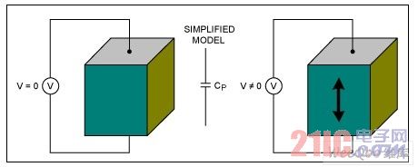
Figure 2. Simplified piezoelectric model
Coulomb's law states that Q = CV, but the capacitance is not constant in the piezoelectric body because the capacitance plate spacing varies with voltage.
When a voltage is applied to the piezoelectric body, the capacitance changes as the distance between the plates changes (Fig. 3A). The piezoelectric body displacement is proportional to the electric field strength, and the electric field strength is a function of the voltage and distance between the plates. The applied voltage maintains a reasonable proportional relationship with the force generated by the piezoelectric actuator (Fig. 3C).
In the range of movement of most piezoelectric actuators, the charge and displacement of the equivalent capacitance of the piezoelectric body are approximately proportional. If there is no leakage current between the equivalent capacitor plates, the displacement can be maintained even if the plates are disconnected from the voltage source.
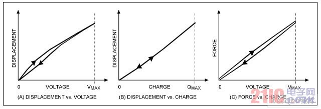
Figure 3. Displacement and force versus applied voltage
The force is proportional to the piezoelectric external voltage (Figure 3). The force (relative to time) is the main factor affecting the tactile response, which determines the user's perception that the use of multilayer piezoelectric bodies can improve the amount of displacement.
Piezoelectric model
The motor system operating in the piezoelectric body can be modeled by a series network of main dielectric capacitors CP connected in parallel by LRC (Fig. 4). Before reaching the resonant frequency, the impedance will drop as the frequency rises as the capacitor rises. Therefore, when the piezoelectric body operates far below the resonant frequency, it can be simulated with only one capacitor CP.

Figure 4. Piezoelectric impedance and frequency
The piezoelectric body can operate at a resonant frequency to meet the need for self-oscillation at a fixed frequency, such as an ultrasonic oscillator. However, piezoelectric actuators for haptic feedback typically operate at locations well below the resonant frequency.
For audio applications, efficiency is the most concerned issue, and tactile feedback is different. The key issue of tactile feedback is not efficiency, but human touch. Vibrations in excess of a few hundred megahertz do not provide good tactile feedback, but consume unnecessary power. Vibrations with a period of more than a few milliseconds can produce a strong touch, but can also produce clicks that are undesired.
Figure 5 shows a typical tactile waveform that simulates the feeling of pressing and releasing a mechanical button. The rising edge of the waveform, P0 to P1, reflects the tactile response of the press; the falling edge, P2 to P3, reflects the released tactile response. The time from P1 to P2 is the duration of the user pressing the mechanical button, which is determined by the user.
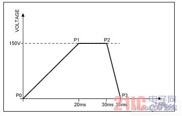
Figure 5. Example of a typical haptic feedback waveform
When building a piezo-based haptic feedback system, the first thing to decide is whether to use a single-layer or multi-layer piezo driver (Figure 6). Table 1 summarizes the comparison of the two piezoelectric types.
Table 1. Comparison of Advantages of Single and Multilayer Piezo Drivers
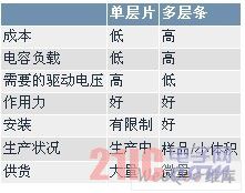
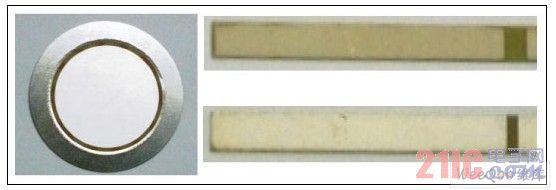
Figure 6. The left picture shows the 100VP-P single-layer piezoelectric sheet (SLD); the upper right picture shows the 120VP-P multilayer piezoelectric strip (MLS); the lower right picture shows the 30VP-P multilayer piezoelectric strip (MLS).
plan selection
Single layer or multi-layer structure?
The information provided in Table 1 suggests the use of a single-layer piezo driver. Single-layer sheets are available in large quantities and are already in mass production, and relatively few layers of piezoelectric bodies are put into production. In addition, the cost of a single-layer piezoelectric body is much lower, which is important in a scheme using a plurality of piezoelectric bodies. For example, many mobile phones on the market have multiple single-layer piezoelectric sheets installed behind the screen. In this case, the cost of using multilayer piezoelectric bodies is much higher.
Is the discrete solution still a single-chip solution?
One of the shortcomings of the piezoelectric-based haptic feedback scheme is the high complexity. A typical piezoelectric solution uses discrete components to implement the entire haptic feedback system. The additional discrete components include a microcontroller, flyback boost, or integrated charge. Pumps, flyback transformers or inductors, as well as various resistors, capacitors, diodes and transistors. The haptic feedback scheme based on DC motors requires little or no external components.
Single-chip haptic feedback schemes such as the MAX11835 offer many advantages over traditional discrete designs: smaller printed circuit board size, lower power consumption, a streamlined bill of materials (BOM), and simple software support. Considering the small size of the piezoelectric body, the MAX11835 is an attractive solution for handheld devices.
Figure 7 shows a block diagram of a single-chip high-voltage haptic feedback drive controller:
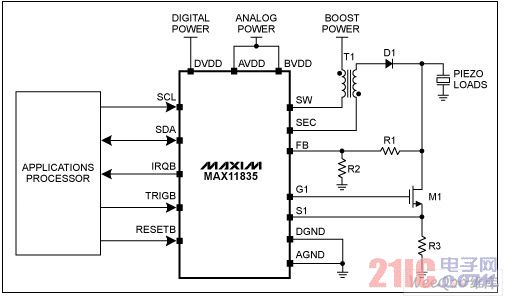
Figure 7. Block diagram of a haptic feedback scheme using a piezo driver
The MAX11835 single-chip optimization solution has the following features:
â— Support single and multi-layer piezo drivers
â— User-definable on-chip waveform storage function (via serial port)
â—On-chip waveform generator
â—Inline DC-DC boost controller
â— Operating voltage range can meet the needs of typical mobile phone batteries
â—Small package size
â—Low power consumption
The importance of power management
Piezoelectrics consume very little power compared to DC motor drivers. However, there are still some other power factor considerations:
â— Each time you touch the power consumed from the main power supply
â—The type of waveform that is touched each time
â—Touch times per second
â— Power consumed by the high voltage boost circuit
The MAX11835 haptic drive controller measures the power dissipation of various piezo drivers and high voltage capacitors. The MAX11835 can play back software-controlled stored waveforms in the feedback loop of the boost converter. The test waveforms include a 100Hz sine wave and a 20Hz ramp.
Figures 8, 9A, and 9B show the output of the MAX11835 driving a 175V 100Hz sine wave, as well as the main winding current of the transformer.
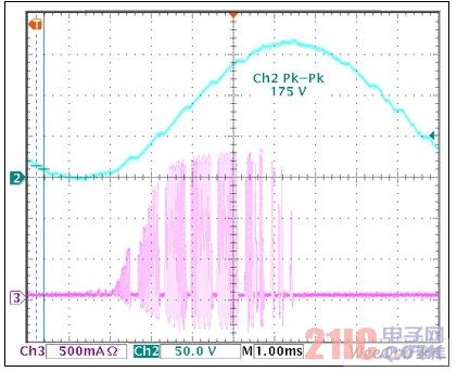
Figure 8. Output voltage waveform and current waveform of the MAX11835 boost supply
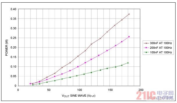
Figure 9A. Power consumption versus load for a 100Hz continuous sine wave
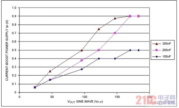
Figure 9B. A plot of peak boost current versus load.
Test conditions: frequency = 100 Hz sine wave; boost supply voltage = 4.2V; boost power supply decoupling capacitor = 10uF; use 6:1 transformer.
Pressing the button is the most common operation. The waveform shown in Figure 10 requires 40ms to charge and 10ms to discharge. Slow charging is not easy to detect while touching the screen, while a quick discharge feels like releasing a mechanical button.
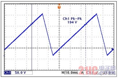
Figure 10. Analog waveform of the pressed button
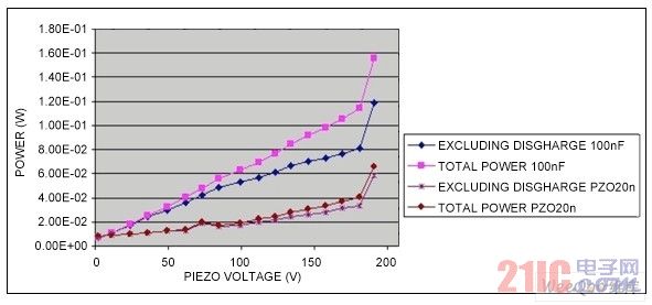
Figure 11. Power vs. Piezoelectric Voltage vs. Single-layer and multi-layer piezoelectrics to simulate button presses. When the voltage exceeds 180V, the primary side clamp of the MAX11835 turns on and the power consumption rises sharply.
The waveform shown in Figure 11 operates continuously. Power consumption decreases linearly as the duty cycle decreases. There is no significant difference between the mechanical load (semi-blocking force) and the piezoelectric body data of the no-load piezoelectric actuator.
Figure 12 shows the efficiency of the MAX11835 boost process, which is measured by dividing the load draw energy by the boost power consumption (VBST).
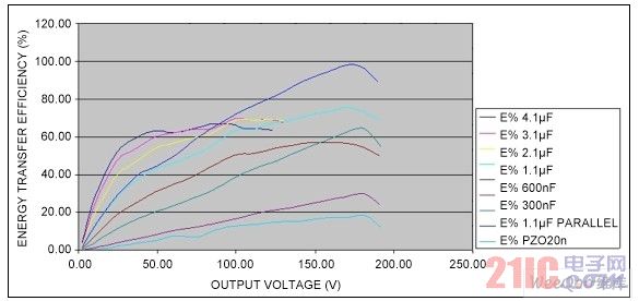
Figure 12. Energy conversion efficiency: energy consumed by the load and energy consumed by the VBST. When the voltage exceeds 180V, the primary side clamp of the MAX11835 is turned on, and the efficiency rises rapidly.
In Figure 12, the efficiency increases as the load capacitance increases because only the boost circuit consumes static power.
MAX11835 Power Consumption vs. Motor Driver Power Consumption
The power dissipation of the MAX11835 is very low compared to motor drivers, which include the Polarization Rotation (ERM), Linear Oscillator (LRA), and voice coil types.
Motor-based drives typically require low voltages (1.8V to 3V) and the current is quite large. In addition, the on/off characteristics of the motor, especially the ERM type, do not have the ideal feedback signal required for analog tactile sensation.
Table 2 and Figure 13 show a large number of measurements of the driver, testing two modes of operation, continuous operation and pulsed operation. The actual situation is usually not a continuous mode of operation, as many touch operations are very short, even if the simulation of the textured surface is simulated.
Table 2. Power consumption of the motor driver
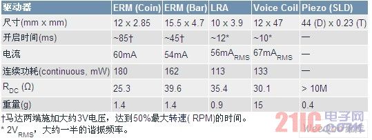
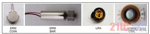
Figure 13. Table 2 comparison of the drive, the relevant data is shown in Table 2.
Figure 14 shows the power consumption for continuous operation. The piezoelectric body in the figure is driven by a continuous sine wave with an amplitude of 180V and a frequency of 100 Hz. Other drives are driven by 3VDC or 2VRMS (LRA and voice coil).
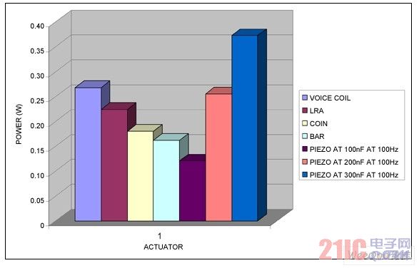
Figure 14. Power consumption for continuous operation of various drivers
Figure 15 shows the power consumption in the pulse mode of operation. The driver is driven by a 50ms pulse to simulate a button press. Piezo driver drives are driven at 180V and other drivers drive at 3VDC or 2VRMS (LRA and voice coil).
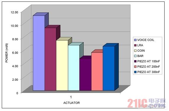
Figure 15. Power consumption of various drivers in pulse mode
in conclusion
Many conclusions can be drawn from the above discussion. Clearly, single-layer (non-multilayer) piezoelectric actuators are currently more attractive designs based on multiple considerations:
Lowest cost
Many channels of supply
Mass production
Custom design
Can be mounted on the back or side of the LCD
The data shows that the haptic feedback circuit should consume detailed power consumption, and the magnitude, type, and duration of the waveform affect the power consumption and tactile response.
The number of touches per second also affects power consumption, whether scrolling or swiping, or tapping or slow typing, all of which affect power consumption. Finally, the measurement results are normalized to one touch per second for comparison.
StormPorto Service
Unlike other suppliers,we accept your job with multiple designs in one panel.Many customers told us they would like to cut cost when they are doing design jobs as the first prototypes may change in next version .Only 1 or 2 units they need for each design.So,our StormProto helps. it includes
.Up to 10 designs per panel.FR4,1.0-1.6mm,1oz,Green solder mask,White overlay,HAL
.Electrical testing
.Standard 5 working days
.Express 2-3 working days
.Two panel size:270*420mm,370*420mm
.1-4 layer to panel .Prototype PCB,2 Layer Eing Board,Supply Board PCB,Black Prototype PCB
Storm Circuit Technology Ltd , http://www.stormpcb.com