Filters are one of the key components in RF systems, primarily for frequency selection—passing unwanted frequency signals to reflect unwanted interfering frequency signals. A classic filter application example is the receiver or transmitter front end, as shown in Figure 1, Figure 2:
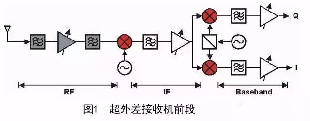
As can be seen from Figure 1, the filter is widely used in the RF, IF, and baseband portions of the receiver. Although the development of this digital technology uses a digital filter to replace the analog band of the baseband part or even the intermediate frequency part, the filter of the radio frequency part is still irreplaceable. Therefore, the filter is one of the essential components in the RF system. There are many ways to classify filters. For example, the characteristics selected by frequency can be divided into: low pass, high pass, band pass, band stop filter, etc.;
According to the implementation, it can be divided into: LC filter, surface acoustic wave/body acoustic wave filter, spiral filter, dielectric filter, cavity filter, high temperature superconducting filter, planar structure filter. According to different frequency response functions can be divided into: Chebyshev, general Chebyshev, Butterworth, Gauss, Bessel function, elliptic function and so on. For different filter classifications, the different characteristics of the filter are described primarily from different filter characteristic requirements. The many different features of the filter described by this multi-classification method of the filter embodies the need for the filter in practical engineering applications, which means that the design needs to be comprehensive when designing for user needs. Consider user needs. When selecting a filter, the first thing to determine is whether a low pass, high pass, band pass or band stop filter should be used. The following is a description of the frequency response characteristics of high-pass, low-pass, band-pass, and band-stop, and their effects, which are classified by frequency.
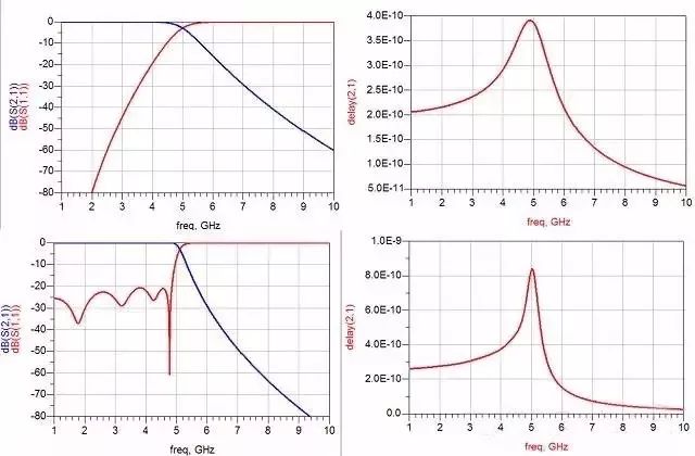
Butterworth Chebyshev bandpass filter
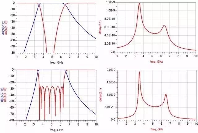
Butterworth Chebyshev high-pass filter
The most commonly used filters are low pass and band pass. Low-pass is widely used in image suppression in the mixer section and harmonic suppression in the frequency source section. Bandpass is widely used in signal selection at the front end of the receiver, spurious suppression after transmitter power amplifier, and spurious suppression of frequency source. Filters are widely used in microwave radio frequency systems. As a functional component, there must be corresponding electrical performance indicators to describe the performance requirements of the system for the component. Corresponding to different applications, there are different requirements for certain electrical performance characteristics of the filter. Describe the filter electrical performance specifications: order (stage) absolute bandwidth / relative bandwidth cutoff frequency standing wave out-of-band rejection ripple loss passband flatness phase linearity absolute group delay group delay fluctuation power capacity phase consistency Amplitude consistency operating temperature range
The electrical performance indicators of the filter are explained one by one below. Order (number of stages): For high-pass and low-pass filters, the order is the sum of the number of capacitors and inductors in the filter. For a bandpass filter, the order is the total number of parallel resonators; for a bandstop filter, the order is the total number of series resonators and parallel resonators. Absolute Bandwidth / Relative Bandwidth: This indicator is typically used in bandpass filters to characterize the frequency range of the filter that can be passed through the filter. The relative bandwidth is the percentage of absolute bandwidth to center frequency.
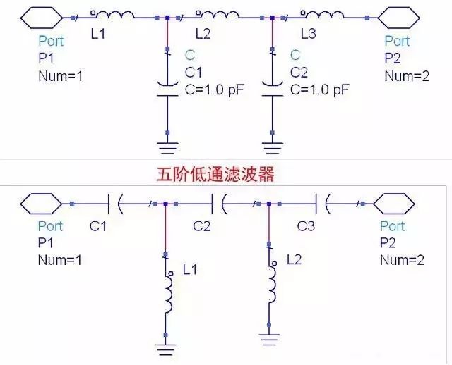
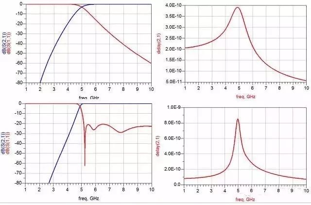
Fifth-order high-pass filter
Cutoff frequency: The cutoff frequency is typically used for high pass and low pass filters. For the low-pass filter cut-off characterizes the highest possible frequency range of the filter; for high-pass filters, the cutoff frequency characterizes the lowest possible frequency range of the filter. Standing wave: S11 measured by the vector network indicates the matching degree of the filter port impedance with the required impedance of the system. Indicates how much of the input signal has failed to enter the filter and is reflected back to the input.
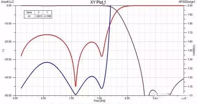
Nine-order low-pass filter simulation curve
Loss: Loss represents the energy lost after the signal passes through the filter, which is the energy consumed by the filter. Passband flatness: The absolute value of the difference between the maximum loss and the minimum loss in the passband of the filter. Characterizes the difference in energy consumption of filters for different frequency signals. Out-of-band rejection: The “attenuation amount†outside the filter passband frequency range. Characterizes the ability of the filter to select unwanted frequency signals. Ripple: The difference between the peaks and valleys of the S21 curve in the passband of the filter. Phase linearity: The phase difference between the phase of the filter passband frequency range and a transmission line equal to the center frequency delay. Characterize the dispersion characteristics of the filter. Absolute Group Delay: The time it takes for a signal to pass from the input port to the output port within the passband of the filter. Group delay fluctuation: the difference between the maximum and minimum values ​​of the absolute group delay in the passband of the filter. Characterize the dispersion characteristics of the filter. Power Capacity: The maximum power that can be input to the passband signal of the filter. Phase Consistency: The difference in phase of the transmitted signal between different filters of the same indicator in the same indicator. Characterize the difference (consistency) between batch filters. Amplitude consistency: The difference in transmission signal loss between different filters of the same indicator in the same indicator. Characterize the difference (consistency) between batch filters. Phase linearity: The phase difference between the phase of the filter passband frequency range and a transmission line equal to the center frequency delay. Characterize the dispersion characteristics of the filter. Absolute Group Delay: The time it takes for a signal to pass from the input port to the output port within the passband of the filter. Group delay fluctuation: the difference between the maximum and minimum values ​​of the absolute group delay in the passband of the filter. Characterize the dispersion characteristics of the filter. Power Capacity: The maximum power that can be input to the passband signal of the filter. Phase Consistency: The difference in phase of the transmitted signal between different filters of the same indicator in the same indicator. Characterize the difference (consistency) between batch filters. Amplitude consistency: The difference in transmission signal loss between different filters of the same indicator in the same indicator. Characterize the difference (consistency) between batch filters.

LC filter
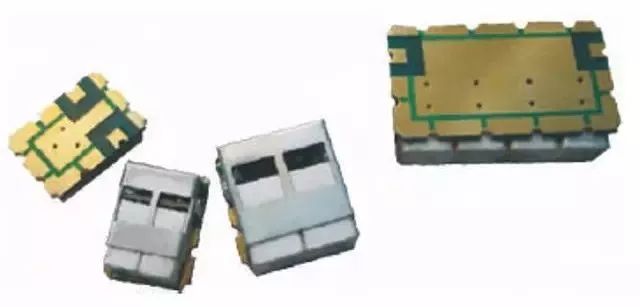
The surface acoustic wave/body-acoustic wave filter sound meter uses a method of converting electric energy into surface acoustic waves and using the acoustic resonance effect to achieve filtering. The surface acoustic wave filter is characterized by a very small volume, a high Q value relative to LC, and is suitable for mass production using a semiconductor process. A filter with an output of around 800MHz is only about one 0805 capacitor. The disadvantage is that the power capacity is small, it is not suitable for small-volume customized products, the development cycle is long, and the research and development cost is high. Sound meter filters are commonly used in end consumer electronics.
Spiral filter
Spiral filter: A spiral filter is a filter with a semi-lumped parameter that uses a self-resonance of a spiral inductor placed in a cavity to implement a resonator, which is coupled by a spatial magnetic field of an adjacent resonator. The advantage is that the volume is smaller than the cavity, and the Q value and power capacity are higher than LC. The disadvantage is that it is difficult to achieve broadband, and the high-frequency part of the inductor is not easy to implement. The spiral filter is usually used in the case of a 20% relative bandwidth below 500MHz, 100W average power, and there are certain requirements for insertion loss.
Dielectric filter
Ripple: The difference between the peaks and valleys of the S21 curve in the passband of the filter. Dielectric Filter The dielectric filter is a half-sense filter implemented with a dielectric-filled quarter-wave short-circuit or a half-open path. The advantage is that the Q value is higher than LC, and a filter with a higher frequency than the LC filter can be realized. The disadvantage is that the parasite is closer and the resonator needs to be customized.
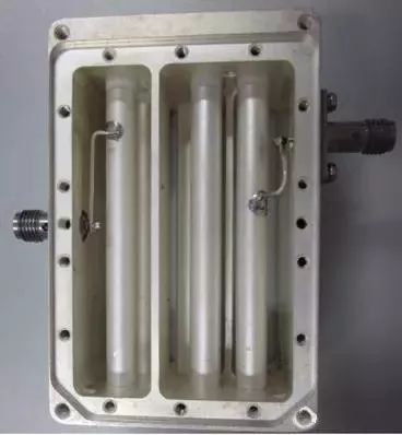
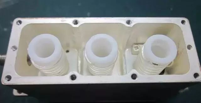
Comb cavity filter
The biggest feature of the interdigital filter is that it can achieve wideband. If a redundant resonant rod is used, the relative bandwidth can be as wide as 60%, considering that the machine is linear. At the same time, in the K-band, the wide-band comb filter machine is basically unable to process and the debugging screw cannot be placed, so the interdigitated structure is usually adopted under this condition. The interdigitated structure is closer to the parasitic passband than the comb, and its parasitic passband is usually around 1.8F0. Under the same volume, the interdigital filter has a larger power capacity than the comb filter. Filters are an essential component of wireless communication systems. There are many kinds of filters, and various filters have different performance characteristics. Therefore, when selecting a filter, it is usually necessary to comprehensively consider the customer's actual use environment and customer performance requirements in order to make a correct, effective, and reliable choice. When the customer's concept of filter index is vague, it is usually necessary to ask the customer volume, loss, frequency of out-of-band suppression, and suppression, power capacity, and so on. According to these simple indicators, the filter type can be basically judged.
The OEM pressure core with high performance and high stability is used as the signal measuring element. The sensor signal is converted into standard signal output after special signal processing. After long-term aging and stability screening, the product performance is stable and reliable. It is applied to the outdoor site with poor environment. At the same time, it can display the field pressure, and the zero point and full range can be moved.
Jb400 pressure transmitter installation interface form can not only be processed according to the user's requirements, but also provide specifications compatible with other brands of transmitters. This series of products are widely used in industrial process control, petroleum, chemical industry, metallurgy and other industries.
Marine Pressure Sensor,Marine Pressure Measuring Sensor,Stainless Steel Marine Pressure Sensor,Pressure Sensor For Marine
Taizhou Jiabo Instrument Technology Co., Ltd. , https://www.taizhoujbcbyq.com