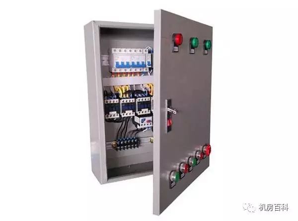
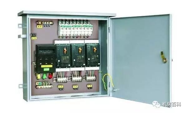
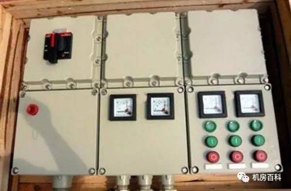
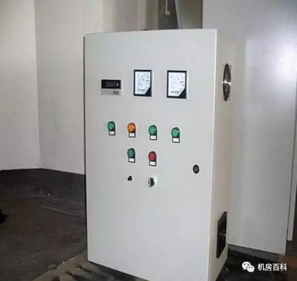
"Distribution box", also called distribution box, is the collective name for the motor control center. The distribution box is to assemble switchgear, measuring instruments, protective electrical appliances and auxiliary equipment in closed or semi-enclosed metal cabinets or screen panels according to the electrical wiring requirements to form a low-voltage power distribution device. During normal operation, the circuit can be switched on or off by means of a manual or automatic switch. In the event of malfunction or abnormal operation, the circuit or alarm is cut off by means of a protective appliance. Measurement instruments can be used to display various parameters in operation, and certain electrical parameters can be adjusted to indicate or signal deviations from normal operating conditions.
Use of distribution box
It is easy to manage and helps to repair when a circuit failure occurs. Distribution boxes and switchboards, distribution boards, and other distribution equipment are centralized devices for the installation of switches and meters. The commonly used distribution box is made of wood and iron plate. Now, where the electricity consumption is quite large, so the use of iron is more. The purpose of the distribution box: Of course, it is convenient to stop, send electricity, play the role of measurement and judgment stop, power transmission.
The distribution box configuration is mainly divided into two parts:
One is the complete set of components, namely the distribution box enclosure and its associated Accessories.
The second is electrical components and related accessories, namely air switches and their required accessories.
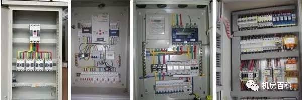
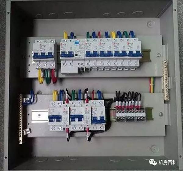
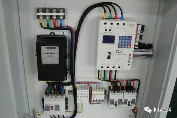
The cabinet has the following components
One, circuit breaker
Circuit breaker: not only the switch, is the main components of the distribution cabinet, commonly used air switch. Leakage switch. Dual power automatic transfer switch.
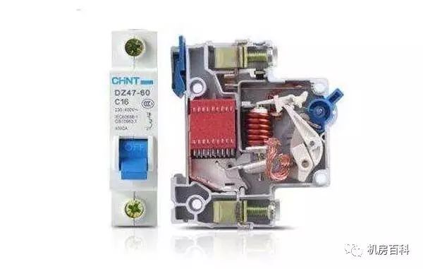
1. Air switch:
A. The concept of air switch:
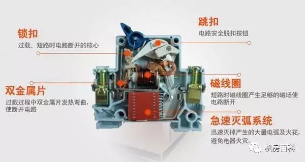
The air switch is also an air circuit breaker, which is used to make, break, and carry fault currents such as rated operating current and short circuit and overload in the circuit, and can quickly break the circuit in the event of overload, short circuit, or undervoltage in the line and load. Reliable protection. The design of the circuit breaker's dynamic and static contacts and contact bars is various, but improving the breaking capacity of the circuit breaker is the main purpose. At present, the use of a certain contact structure to limit the current limiting principle of the short-circuit current peak at the time of breaking has a significant effect on improving the breaking capacity of the circuit breaker and has been widely adopted.
B. How the air switch works:
Automatic air switches, also known as low-voltage circuit breakers, can be used to switch on and off the load circuit and can also be used to control motors that do not start frequently. Its function is equivalent to some or all of the functions of the switch, over-current relay, voltage-loss relay, thermal relay and leakage protector, etc. It is an important protection appliance in low-voltage distribution network.
Automatic air switch has a variety of protection functions (overload, short circuit, under voltage protection, etc.), action value is adjustable, high breaking capacity, easy operation, safety, etc., so it is widely used.
2. Leakage protection switch:
A. Leakage protection switch concept:
It not only has the function of leakage protection, but also touches the charged body and trips it to ensure personal safety. It is the main function of the leakage protector. If the electrical equipment is not well insulated and leaks to the housing, the leakage protector will trip and avoid touching the human body. At the same time with current off function, overload protection and short circuit protection.
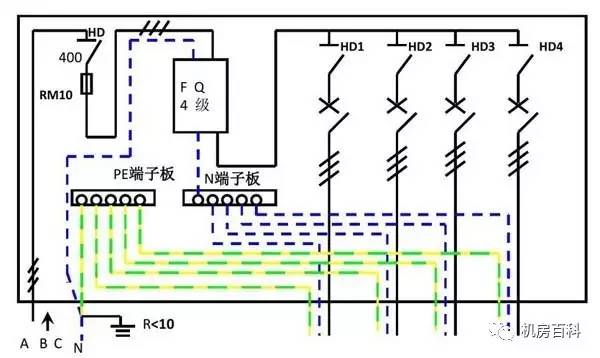
B. The working principle of the leakage protection switch:
Leakage protector working principle diagram. LH is a zero-sequence current transformer, which consists of a core made of permalloy and a secondary coil wound on a ring core to form a detection element. The power line and the neutral line pass through the round hole to become the primary coil of the zero-sequence transformer. The rear outlet of the transformer is the protection scope.
C. The role of leakage protection switch:
1. When a leakage or ground fault occurs in an electrical device or a line, the power supply can be cut off before the person has touched it.
2. When the human body touches a charged object, it can cut off the power supply within 011s, so as to reduce the degree of damage of the current to the human body.
3. It can prevent fire accident caused by leakage.
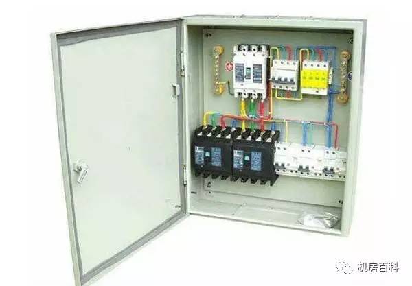
3. Dual power automatic transfer switch:
Dual power automatic transfer switch concept:
Dual power automatic transfer switch is an automatic switching system for power selection. After the first line fails, the dual power automatic transfer switch automatically switches to the second power supply to the load. If the second line fails, the dual power automatic transfer switch automatically switches to the first position. The road supplies power to the load.
Suitable for UPS-UPS, UPS-generators, UPS-city power, city power - city power and other arbitrary two-way power conversion.
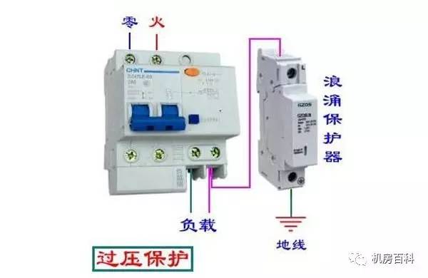
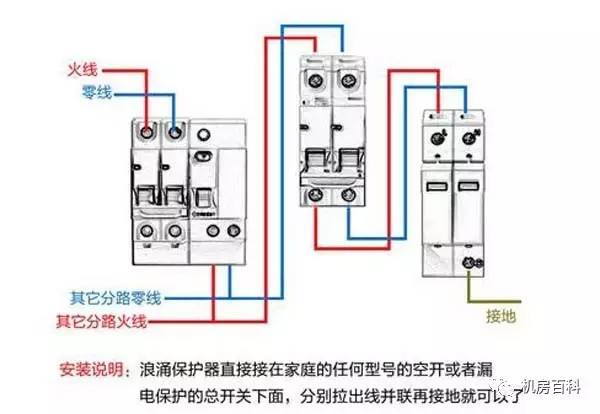
Second, surge protectors:
A. Surge protector concept:
Surge protection device, also called lightning protection device, is an electronic device that provides security protection for various electronic devices, instrumentation, and communication lines. When a sudden current or voltage suddenly occurs in an electrical circuit or a communication line due to external interference, the surge protector can conduct the shunt in a very short time, thereby avoiding the damage of the surge to other equipment in the circuit.

B. Surge basic knowledge:
The main function of the surge protector system is to protect electronic equipment from "surge" damage. Therefore, if you want to know the function of a surge protector, you need to clarify two issues: What is a surge? Why do electronic devices need their protection?
Surge is also called surge, as its name suggests is the momentary overvoltage beyond the normal operating voltage. In essence, surges are a kind of intense pulses that occur in just a few millionths of a second. Possible causes of surges are: heavy equipment, short circuits, power switching or large engines.
Surge or transient voltage means that the voltage exceeds its rated level significantly during the flow of electrical energy. In the United States, the standard voltage for general home and office environment wiring is 120 volts. If the voltage exceeds 120 volts, there is a problem and the surge protector helps prevent the problem from damaging the computer.
C. The role of surge protectors:
The first line of defense should be a large-capacity power surge protection device connected between the incoming phase of the user's power supply system and the ground. It is generally required that the power protector of this stage has a maximum impact capacity of 100 kA/phase or more, and the required limiting voltage should be less than 2800 volts. We call it CLASS I Power Surge Protector (SPD).
These power surge protection devices are designed to withstand high currents and high energy surge energy absorption due to lightning and induced lightning strikes. They can divert a large amount of inrush current to the earth. They only provide limited voltage (inrush current flows through the SPD, the maximum voltage appearing on the line becomes the limiting voltage) for medium-level protection, because the CLASS I protector is mainly for the absorption of large inrush currents. They alone cannot completely protect the sensitive electrical equipment inside the power supply system.
The second line of defense should be a power surge protector installed at a branch distribution facility that supplies power to critical or sensitive consumer equipment. These SPDs provide better absorption of residual surge energy that has passed through the customer's power supply inlet surge arresters, and have excellent suppression of transient overvoltages. The power surge protection device used here requires a maximum impact capacity of 40 kA/phase or higher, and the required limit voltage should be less than 2000V. We call it CLASS II power surge protector. The general user power supply system can reach the second level of protection to meet the requirements for the operation of electrical equipment.
The last line of defense can use a built-in power surge protector in the internal power supply section of the electrical equipment to achieve the goal of completely eliminating transient transient overvoltages. The power surge protection device used here requires a maximum impact capacity of 20 kA/phase or lower, and the required limit voltage should be less than 1800V. For some particularly important or particularly sensitive electronic devices, it is necessary to have third-level protection. At the same time, it can also protect the power equipment from the transient overvoltage generated inside the system.
Third, the power meter:
A. The concept of a power meter:
The electric energy meter usually used by an electrician is a meter used to measure electric energy, commonly known as a power meter.

B. How the meter works:
The working principle of a mechanical watt-hour meter: When the watt-hour meter is connected to a circuit, the magnetic flux generated by the voltage coil and the current coil passes through the disk. These magnetic fluxes are out of phase in time and space, and eddy currents are respectively induced on the disk. Due to the interaction between the magnetic flux and the eddy current, a rotating torque is generated to cause the disk to rotate. Due to the braking action of the magnetic steel, the rotation speed of the disk reaches a uniform speed. Since the magnetic flux is proportional to the voltage and current in the circuit, the disk Under its action, it is proportional to the rotational speed of the load current, and the rotation of the disk is transmitted to the meter through the worm. The number of the meter is the actual electric energy used in the circuit.

2 The basic principle of electronic power meter: electronic meter is the use of electronic circuits / chip to measure electrical energy; with a voltage divider or voltage transformer to convert the voltage signal into a small signal for electronic measurement, with shunt or current mutual inductance The device converts the current signal into a small signal that can be used for electronic measurement, uses a dedicated electric energy measurement chip to perform analog or digital multiplication of the converted voltage and current signals, and accumulates the electric energy, and then outputs a pulse signal whose frequency is proportional to the electric energy. The pulse signal drives the stepper motor to drive the mechanical meter display, or it is sent to the microcomputer for digital display.
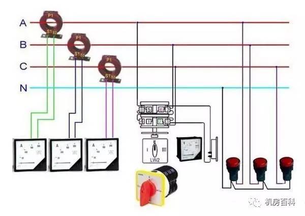
Fourth, ammeter:
A. How the current meter works:
The flow table is made according to the force of the magnetic field in the magnetic field of the energized conductor. When there is a current passing through, the current passes through the magnetic field along the spring and the rotating shaft, and the current cuts the magnetic induction line, so the magnetic field force acts to deflect the coil and drive the rotation shaft and the pointer to deflect. Since the magnitude of the magnetic field force increases as the current increases, the magnitude of the current can be observed by the degree of deflection of the pointer. This is called a magnetoelectric current meter.
B. Rules for the use of ammeters:
1 The ammeter should be connected in series in the circuit (otherwise short circuit.);
2 The measured current should not exceed the ammeter's range (you can use the test method to see if the range is exceeded.);
3 Absolutely not allowed to connect the ammeter to the two poles of the power supply without using electrical appliances. (The internal resistance of the ammeter is so small that it is equivalent to a wire. If the ammeter is connected to the two poles of the power supply, the pointer will smash, and if it is heavy, it will burn out. Ammeter, power supply, wires.).
4 see the needle stay (it must be viewed from the front)
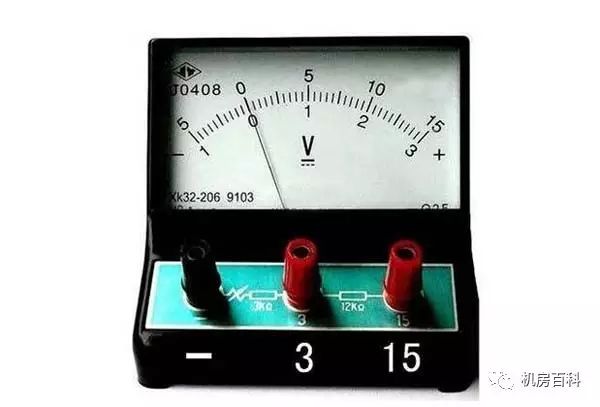
V. Voltmeter:
A. The concept of voltmeter:
Voltmeter is an instrument for measuring voltage. Commonly used voltmeter - voltmeter symbol: V. There is a permanent magnet in the sensitive ammeter. A coil consisting of wires is connected in series between the two terminals of the ammeter. Placed in the magnetic field of the permanent magnet and connected to the pointer of the watch through the transmission. A voltmeter is a fairly large resistor, ideally thought of as an open circuit.
B. Voltmeter working principle:
The voltmeter is assembled using an ammeter. The internal resistance of the ammeter is very small. If a large resistor is connected in series, it can be directly connected to two points where the voltage needs to be measured. According to the relation of Ohm's law, the current displayed by the ammeter is proportional. External voltage so you can measure the voltage
C. Use of voltmeter:
Voltmeter can directly measure the power supply voltage, when the voltmeter is used, it should be connected in parallel in the circuit. When using the voltmeter, pay attention to the following points: (1) When measuring the voltage, the voltmeter must be connected in parallel at both ends of the circuit under test;
(2) The correct range is selected. The measured voltage should not exceed the voltmeter's range. When used in parallel with the circuit; if connected in series, the measured power EMF.
However, several components mentioned above are the most basic components in the distribution box. In the actual production process, other components will be added according to the different uses of the distribution box and the use requirements of the distribution box. , such as: AC contactors, relays, time relays, push buttons, signal indicators, KNX intelligent switch modules (with capacitive load) and background monitoring systems, intelligent fire evacuation lighting and background monitoring systems, electrical fire/leakage monitoring detectors And background monitoring system, EPS power battery and so on.
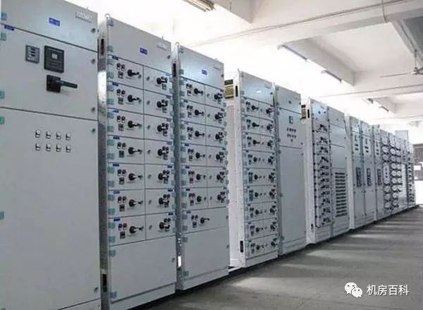
Classified by structural features and uses:
(1) Fixed panel switchgear, often called switchboard or power distribution panel. It is an open-type switchgear with panel cover. It has a protective function on the front. It can still touch live parts on the back and side. It has a low protection level and can only be used in industrial and mining enterprises with low requirements for continuity and reliability of power supply. Substation centralized power supply.

(2) Protective (ie, closed) switchgear refers to a low-voltage switchgear that is enclosed on all sides except the mounting surface. The electrical components such as switchgear, protection and monitoring control of the cabinet are all installed in a closed enclosure made of steel or insulating material and mounted on a reliable wall or off the wall. There may be no isolation between each circuit in the cabinet. It may also use grounded metal plates or insulation plates for isolation. Normally, the door is mechanically interlocked with the main switch operation. There is also a protected type switchgear (ie, a console) with control, measurement, and signal electronics. Protective switchgear is mainly used as a power distribution device at the process site.

(3)Drawer-type switchgear cabinets, which are made of closed plates with steel plates, and the electrical components of the inlet and outlet circuits are all installed in drawers that can be pulled out to form functional units that can fulfill certain types of power supply tasks. Between the functional unit and the bus or cable, separated by a grounded metal plate or a plastic function board, the busbar, the functional unit and the cable are formed in three areas. There are also isolation measures between each functional unit. Drawer-type switchgears have high reliability, safety and interchangeability. They are relatively advanced switchgears. The switchgear currently produced is mostly a drawer-type switchgear. They are suitable for industrial and mining enterprises and high-rise buildings requiring high reliability of power supply as a centralized power distribution center.
(4) Power, lighting distribution control box, mostly closed vertical installation. Due to different occasions, the degree of protection of the shell is also different. They mainly serve as power distribution devices for industrial and mining enterprises.
The distribution box installation requirements are:
The distribution box is made of non-combustible materials; production sites and offices with low risk of electric shock can be equipped with open type switchboards; processing workshops, casting, forging, heat treatment, boiler rooms with high risk of electric shock or poor working environment The enclosed cabinets shall be installed in places such as woodworking houses, etc.; in the dangerous working places with conductive dust or flammable and explosive gases, closed or explosion-proof electrical facilities must be installed; all electrical components and meters of the distribution box must be installed. The switches and lines should be arranged neatly, firmly installed, and easy to operate. The floor of the floor-mounted board (box) should be 5~10 mm higher than the ground; the center height of the operating handle is generally 1.2~1.5m; the obstacle is within the range of 0.8~1.2m in front of the box; the connection of the protection wire is reliable; Bare electric exposure; must be installed on the external surface of the box or electrical components on the distribution board, must have a reliable screen protection.
Operating procedures
(1) The power distribution cabinet is the normal operation of the ship's distribution center and the equipment. Any unrelated personnel must not move the switches on the board.
(2) After the generator sets are started, they should be slowly accelerated manually using the power screen speed-up switch until the generator enters the normal operating state and the voltage and frequency reach the specified value before they can be switched on and transmitted.
(3) After the distribution board enters the power distribution state, the power screen speed-up switch shall not be arbitrarily pulled, and the air circuit breaker's latch switch shall not be used in non-emergency situations.
(4) Parallel operation of generators should be operated strictly in accordance with the conditions and requirements of parallel vehicles. Attention should be paid to the occurrence of reverse power (counterflow) and parallel failure.
(5) When the engine is shut down, the load of the generator shall be cut off first, and then the vehicle shall be stopped without load and shall not be stopped directly with the load.
(6) When interleaving the shore power, the power switches of the shore screen should be cut off first, and then the correctness of the wiring and phase sequence should be checked. Only when the correctness is confirmed can the conversion of shipboard power be implemented and no load operation is allowed.
(7) The switchgear should be cleaned and maintained regularly so that the equipment is always in good working condition.
(8) When the generators work, when the engineers conduct the operation of the distribution board, they should concentrate their thinking and exercise caution in order to prevent accidents from occurring, otherwise they will be held responsible for personal accidents.
(9) The charging and discharging board is the shipboard emergency switchboard. On-duty personnel should constantly check their working conditions and ensure that the low-voltage power is sufficient at any time. The on-board instrumentation is used to grasp the working status of the magnetic saturation regulator.
(10) During normal navigation, each switch of the distribution board shall be connected to ensure that the generator can be started at any time and can be put into use at any time when it is required.
Secondary wiring process
1, according to the schematic diagram, not in the same position to the terminal, do not connect a terminal to 3 lines. Debugging is not the case. It can only be done one by one according to the schematic.
(1) Selection of wire cross section
The voltage of the mains (AC 220V) circuit is 1.5 mm 2 ; the current loop is 2.5 mm 2 . The battery is generally 1.5 square millimeters.
(2) When wiring, check whether the signals at the two ends of the wire correspond to each other to avoid unnecessary errors.
(3) The most important thing is to understand the schematic and wiring diagram.

2, if it is a novice to first look at plans, organize their own ideas, but you can also check the drawings have no problems, do not understand where you can first understand, this is conducive to the line. Then start wiring. The entire wiring process needs careful attention. Of course, if you are veteran, you need not say so much.
Construction personnel should carefully read and familiarize themselves with the secondary line symbols, and check the secondary wiring diagram with the schematic diagram to ensure that the wiring diagram is correct.
The requirements for the secondary wiring construction: construction according to the figure, correct wiring; wire and electrical components using bolted, plugged, welded or crimped, etc., should be solid and reliable, good wiring; wiring neat and clear, beautiful; good insulation of the wire , No damage; cabinet wire should not have connectors; circuit number is correct, clear writing.
The selection of cable core cross-section should also meet the following requirements:
(1) Current loop: The accuracy of the current transformer should be rated. At this time, if there is no reliable basis, the maximum short-circuit current can be determined according to the current capacity of the circuit breaker.
(2) Voltage loop: When all protective devices and safety automatic devices are actuated (taking into account the development, the maximum voltage transformer load), cable voltage drop from the voltage transformer to the protection and automatic device screen should not exceed the rated voltage of 3 %.
(3) Operating circuit: Under the maximum load, the voltage drop from the busbar to the equipment should not exceed 10% of the rated voltage.

2. The secondary winding of the current transformer is not allowed to open, and the secondary side of the voltage transformer should not be short-circuited before the secondary wiring. You should familiarize yourself with the drawings:
(1) Schematic diagram (indicates the working principle and interaction of each circuit. The drawing soon shows the connection of the components in the secondary circuit, and also shows the connection with the primary circuit)
(2) Expanding the map
(3) Terminal layout
(4) Installation wiring diagram
Heavy-duty connectors are designed to withstand the harshest and most demanding industrial environments, and are tougher, stronger, and more resistant than conventional connectors. Compared with traditional connection method, using heavy-duty connector can save 20-30% installation cost for machining center; Increased production efficiency, and reduce wiring error rate.
Hd Series Connector,25 Pin Heavy Duty Connector,High Pin Count Connector,64 Pin Heavy Duty Connector
Kunshan SVL Electric Co.,Ltd , https://www.svlelectric.com