One of the ten pitfalls of the operational amplifier is rail-to-rail. Initially, I thought that choosing a rail-to-rail op amp would solve the issue of the output voltage not reaching the power rail. While it did help the op amp get closer to the power rail, there was still a hidden pitfall waiting for me.
Looking at the specifications of a rail-to-rail op amp from a particular company: "High-speed (>50MHz) rail-to-rail op amps support lower supply voltages, closer power rail swings, and wider dynamic range." Do you notice the phrase "closer to the rail of the supply rail"? This means that while the op amp can get near the power rail, it may not actually reach it.
Take a look at the datasheet for a rail-to-rail op amp:

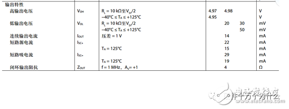
Even though the datasheet shows the output voltage isn't exactly 5V, the reason lies in the output stage of the op amp. It can be simplified to a structure involving MOS transistors. Due to the on-resistance of the MOS transistors, when a current flows through them, a voltage drop occurs. Hence, the output voltage is less likely to reach the power supply rail, especially under higher loads.
Therefore, a rail-to-rail op amp doesn’t completely allow the output to reach the power supply value. When using it, one needs to consider the load and temperature (which affects the on-resistance) to determine how close the output can get to the rail.
Next is the second pitfall of the op amp—non-negligible input bias current. I designed a voltage divider circuit expecting an input of 1V and an output of 2V. However, during testing, the output was consistently more than 6.7mV off. This was problematic when feeding into a 12-bit 3V-range ADC, causing more than 600 counts of error.
The positive and negative inputs of the op amp produce input bias currents due to TVS leakage current and transistor input bias current. These bias currents, combined with external resistors, create a bias voltage that outputs to the backend, causing an error. Choosing a BJT-based op amp with a large input bias current can lead to significant backend errors.
For instance, some op amps are notorious for their large input bias currents, making them unsuitable for precision applications. Compensation can only reduce the offset voltage, and the difference between the positive and negative input bias currents is called the offset current. In high-precision or small-signal sampling, a low-offset current op amp should be selected. Adding a compensation resistor introduces a new noise source, so careful consideration is required.
The input bias current is one of the primary errors of the op amp. Other error sources affecting the backend are also worth noting.
Third, the third pitfall of the op amp—rapid decline in PSRR. As a rookie engineer, I never considered PSRR in my op amp designs. Once I learned about it, I started selecting op amps with higher PSRR based on cost considerations.
For example, this op amp boasts a PSRR of 160dB:
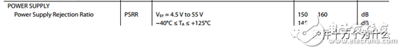
According to the calculation formula:

Even if the supply voltage varies between 4.5V and 5.5V, the effect on the op amp's output is only 10nV.
Unfortunately, this metric refers to the DC change of the power supply voltage and does not account for AC changes like ripple. In practice, this indicator significantly deteriorates under AC conditions. What’s stated in the specs is only for DC changes. Here’s how it looks under AC conditions:
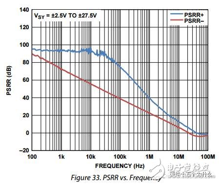
At a 500kHz switching frequency ripple, PSRR+ degrades to just 50dB. Assuming a ripple size of 100mV, the impact on the backend becomes 0.3mV. For small signal acquisition applications, this error is unacceptable. Some applications even add a low-pass filter at the op amp power inlet (but note the resistor power and thermal noise).
Fourth, the chaotic compensation capacitor. An “old engineer†once told me that adding a capacitor to the feedback circuit would prevent oscillations. Following this advice, I added a small capacitor to all my circuits, believing it made me more professional.
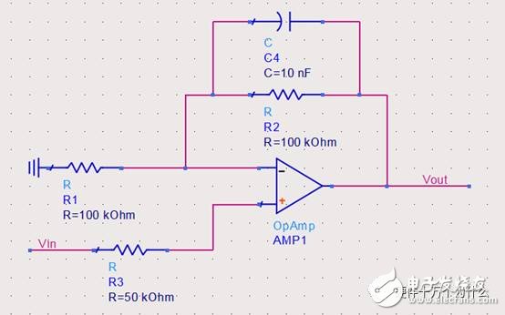
One day, I wanted to amplify a 100kHz signal. Following the same approach, I added a capacitor. The signal became abnormal because the capacitive feedback impedance dropped below 200Ω for a 100kHz signal, changing the amplification factor.
However, the real issue is: do you really need a compensation capacitor?
First, there’s a pole inside the op amp (caused by RC low-pass), leading to a phase change of up to -90°:
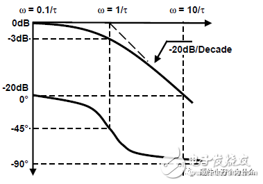
Adding another pole further changes the phase, potentially increasing it to -180°, leading to instability. This is the root cause of oscillation. For voltage negative feedback op amps, instability occurs when the loop gain Aβ equals 1 and the phase is -180°.
To counteract this, a zero can be added externally to pull down the phase. However, the distributed capacitance on the pins is usually small, making the loop gain Aβ=1 occur at very high frequencies, far from the op amp's operating range. Many op amps already have high phase margins, so additional compensation capacitors aren’t necessary.
Finally, the fifth pitfall—common mode input range issues. I once faced a problem where the preamplifier signal fed into the ADC had a range of 0.3V-1.5V. Using a single 5V power supply op amp, some boards showed outputs lower than expected when the input was near 1.5V.
After discussing with the hardware team, we decided to switch to a different op amp. Luckily, we eventually found a working solution without understanding the underlying principles.
Looking at the op amp’s common-mode input range:
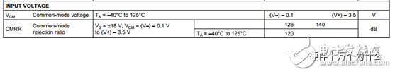
The common-mode input range specifies the interval within which the op amp operates linearly. When the input voltage is outside this range, the output may not follow the input accurately.
For a follower circuit, due to negative feedback, the positive and negative input terminals have nearly the same voltage. With a common-mode input range of -0.1V to 5V, the op amp struggles to maintain linearity when the input is around 1.5V.
Why does this happen? Let’s look at a transistor amplifier circuit, part of the op amp:
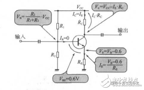
As the input voltage increases, the collector-emitter current changes, affecting the output voltage. If the input voltage exceeds a certain threshold, the amplifier saturates, leading to a fixed or clipped output voltage.
In conclusion, understanding these pitfalls helps avoid unnecessary errors in op amp design.
Pipe Precision Parts
Pipe fittings are the general name of the parts and components that play the role of connection, control, change direction, shunt, seal and support in the pipeline system. A pipe fitting is a part that joins pipes into a pipe.
It mainly includes the following:
1. Pipe fittings used for connecting pipes with each other are: flange, splice, pipe hoop, clamp, sleeve, throat hoop, etc.
2. Pipe fittings that change the direction of the pipe: elbow and bend.
3. Pipe fittings for changing pipe diameter: reducing pipe (reducing pipe), reducing elbow, branch pipe table and reinforcing pipe.
4, add pipe branch fittings: three, four.
5. Pipe fittings for pipeline sealing: gasket, raw material belt, thread hemp, flange blind plate, pipe plug, blind plate, head, welding plug.
6. Pipe fittings for pipe fixing: clasp, hook, lifting ring, bracket, bracket, pipe card, etc.
Pipe Precision Parts,Custom Pipe Parts,Fingerprint Door Lock,Automobile Exhaust Pipe
Tianhui Machine Co.,Ltd , https://www.thcastings.com