Based on a brief introduction of the fully autonomous soccer robot game system, this paper analyzes the shortcomings of the traditional vision system, and designs the CMOS image sensor 0v7620, SRAM frame memory IS61LV25616, CPLD/FPGA controller EPF10K10LC84-3 and DSP device tms320vc5416. The design of the new embedded image sampling processing system. The transformation method from RGB space to HIS space is proposed, which obviously improves the speed and reliability of the soccer robot vision system.
1 Overview of fully autonomous soccer robotsFira's RoboSot group is a fully autonomous soccer robot. The fully autonomous soccer robot competition system is actually a self-operating trolley. Since the autonomous robot is loaded with a complete control system, it can completely collect and process the surrounding environment information and make behavior decisions without the need of external computing power. A color camera is usually mounted on the top or other parts of the robot, and the lens can be swung left and right and pitched up and down to provide color video information for a certain range of viewing angles. In addition, the robot is equipped with ultrasonic or other sensors for distance detection and obstacle detection of the environment. When multiple robots participate in the competition, in order to realize communication between the robots, a wireless communication system should be installed so that it can share the detected environmental information, thereby forming a cooperative system of multiple robots. The robot should also be equipped with a rechargeable battery pack to provide power to embedded computers, sensors, drive motors, and the like.
The characteristics of the fully autonomous soccer robot competition are: it is not allowed to set the global vision system directly above the playing field or other non-robot body, but the camera is installed on the body of the robot, so that the camera can only provide part of the information of the playing field. The robot needs to constantly shake and pitch the camera lens, and if necessary, twist the body to search for the information you need.
The current soccer robots often use off-the-shelf single-board machines (such as PC104) and are equipped with image capture cards, wireless communication network cards, motor drive cards and other boards. This method can not obtain the hardware schematic of the motherboard and the supporting board and the BIOS, board driver and other details of the motherboard, so it is not only bulky, but also because of the limitations of hardware and driver software, it is difficult to achieve the optimal speed requirements of the soccer robot. Reliability is not high. The underlying hardware and underlying control software of the complete control system of the soccer robot are self-developed, although the degree of freedom and flexibility are high, but the workload is large. This paper introduces the soccer robot vision system based on 0v7620 image sensor.
2 Robosot vision subsystem principleFigure 1 shows the hardware block diagram of an embedded vision subsystem. In the figure, the CMOS image sensor mounted on the robot converts the "course" information into an electrical signal, and converts it into a digital signal through the video capture chip, then performs the underlying data processing in FleA, and then feeds it into the SRAM frame memory under its management. After reading the data in the SRAM memory and performing high-level processing, the DSP transmits the processing result to the decision subsystem through the MeBSP port of the DSP. When the connection with the decision system is less than 15 meters, the McBSP port can be used to simulate the RS232 signal to realize communication; when the distance is large, RS422 or wireless communication can be adopted.
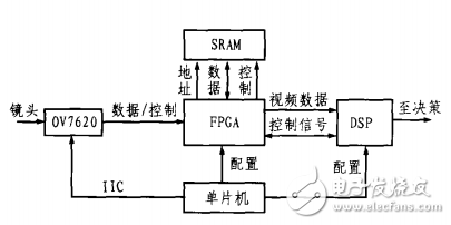
Autonomous soccer robot vision system hardware block diagram
2.1 Image sensor selection
CCD camera devices have dominated the image sensor market due to their high illumination sensitivity, low noise, and small pixel size. In contrast, CMOS image sensors have historically been unable to compete with CCD technology due to shortcomings such as low sensitivity, low signal-to-noise ratio, and large pixel size. However, with the continuous development of CMOS large-scale integrated circuit technology, these shortcomings have been gradually overcome. The high integration, low manufacturing cost, single power supply (3.3V or 5v), low power consumption and low pixel defects of the CMOS device make it ideal for the vision system of autonomous mobile soccer robots. The system uses the cmos color image sensor 0v7620 from Omnivision. The maximum resolution of this sensor is 664 & TImes; 492. It can work not only in progressive scan mode, but also in interlaced mode. The 0v7620 can configure the on-chip registers via the I°C bus to output RGB raw data. After the system is powered on and reset, the I°C bus signal is generated by the I/O port of the MCU to initialize the 0v7620 working register, and then the OV7620 can start outputting the image signal as required, including the line sync signal HREF, the field sync signal VSYNC, and the pixel. Clock signal PCLK and digital image signal.
2.2 Timing Control and Image Preprocessing
After the synchronization and image data signals output by the OV7620 are connected to the CPLD/Flea chip, the underlying preprocessing can be performed here, and the signal is also stored in the frame memory SARM under its control.
The Flea chip selects Ahem's EPFIOKIO to receive the line sync signal HREF, the field sync signal VSYNC, the pixel clock signal PCLK and the image data signal, and simultaneously generates the SRAM address signal and the write signal. In addition, the video data can be pre-processed or directly stored in the SRAM frame memory under the control of the FPGA. The FPGA notifies the DSP to read the data after processing one field or one frame of data. Tms320vc5416 uses the read statement to obtain the video data from the SRAM, and transmits the position, velocity and direction information of the processed robot (car) and the ball to the decision system via the McBSP port of the DSP.
2.3 Frame Memory Selection
There are usually three types of video caching schemes.
The first is a dual port RAM mode. Dual-port RAM has two independent sets of data, address and control buses so that it can be read and written simultaneously from both ports without interfering with each other, and video data can be written from one port and DSP (or other processor) from another One port is read. Dual-port RAM achieves high transmission speeds and has the advantage of random access. The disadvantage is that large-capacity high-speed dual-port RAM is difficult to obtain and expensive, and requires a large number of FPGA pins.
The second is FIFO FIFO. The FIFO memory is like a data pipe. Data flows from one side of the pipe to the other side, and the first incoming data flows out first. The FIFO has two sets of data lines and no address lines, which can be written at one end and read at the other end. The data is sequentially moved therein, thereby achieving high transmission efficiency and facilitating PCB layout due to the omission of address lines. The disadvantage is that only the data can be read and written sequentially, so it appears to be rather rigid, and the high-capacity high-speed FIFO mostly uses dynamic RAM technology to refresh the control circuit.
The third is the high-speed SRAM switching method. The high-speed SRAM has only one set of data, address and control bus, which can be connected to the video sample and DSP through the tri-state buffer gate. When video sampling is performed, the data, address and control bus of the SRAM can be switched to the sampling circuit and controlled by the sampling circuit, and the data, address and control bus of the DSP are in a high impedance state with respect to the SRAM; The SRAM data, address and control bus are switched to the DSP side for the DSP to read and write. At this time, the data, address, and control bus controlled by the sampling circuit are in a high-resistance state relative to the SRAM. The advantage of this method is that the SRAM can be randomly accessed, and the large-capacity high-speed SRAM is easy to obtain, and the price is moderate. The disadvantage is that the switching control circuit is relatively complicated, and can only be read and written by video sampling and DSP. To this end, a dual-body storage alternate access scheme can be introduced, that is, an additional SRAM frame memory is added to form a dual-body storage area. In this way, the two chips can alternately sample and exchange data with the DSP, so that sampling and DSP read data simultaneously.
Considering the performance, price and convenience of the above three cache schemes, this design uses the third scheme and selects an IS61LV25616 chip to achieve.
2.4 video processing DSP
The video processing uses TI's tms320vc5416 to read the video data in the SRAM, and calculates the position, direction and speed of the robot and the ball through software, and then transmits the data to the decision system. The tms320vc5416 has a clock rate of up to 160 MIPS and an advanced command system. Under the "collaboration" of the FPGA, the video data of 10 frames (20 fields) or more can be processed every second, thus ensuring the real-time performance of the game. After the DSP is powered on, the internal bootloader program runs first, and the programs and tables stored in the off-chip FLASH are sent to the on-chip RAM for operation. This can process more than 20 frames of video data per second.
2.5 single chip microcomputer
The MCU selects the AT89C51/AT89C52 which can externally expand the FLASH ROM. The microcontroller has three functions: control of the OV7620, configuration of the FPGA, and startup of the DSP. Since the EPF10K10 saves configuration data in the SRAM during operation, the SRAM is easily lost. Therefore, the SRAM cell must load the configuration data after the device is powered up and initialize its memory and I/O pins after configuration is complete. Once initialized, the device can enter user mode and begin system operation. In the development and debugging phase, the device can be configured by downloading the cable, and when the entire system is designed, it can be configured by the microcontroller system. In this way, the data solidified in the microcontroller system can be configured on the FPGA chip when the system is powered up.
3 software principle and debuggingSince the OV7620 outputs RGB signals, this signal can be directly used for image segmentation. However, the components of the RGB space have a high correlation, and the dispersion of the near-points of the colors is not suitable for the robot soccer system. For this purpose, an HSI space with a clear physical meaning can be used. H in the space model is the hue, corresponding to the dominant wavelength of light; S is the saturation, corresponding to the degree of white light blending in the color; I is the light intensity, corresponding to the brightness of the light. The HSI space model uses H as the main segmentation parameter, but when I is small, the value of H tends to be uncertain. Therefore, H cannot be used as the sole identification basis, but I should also be used as the identification basis. When implemented, the RGB space can be transformed into the HSI space using the following formula.
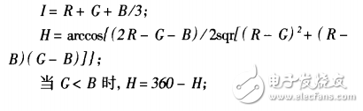
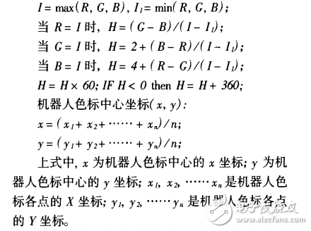
Since there is an inverse trigonometric function in the above operation, it is difficult to implement with an FPGA. To this end, the following simplified formulas can be used to calculate H and I without affecting the identification conclusion:
The development software used by the FPGA is MAX+PLUSI. The software is a super-integrated environment that integrates design, input, compilation, simulation and programming. FPGA design has four basic phases: design input, design compilation, design verification, and device programming. The design should first generate the top-level structure diagram according to the logic function of the system, and then divide it into several small modules for the next-level design. Next, you can analyze its logic function from top to bottom, design and compile from the bottom layer, and then verify the waveform for each level. Device programming is performed when the logic function of the last top-level module meets system timing requirements in waveform simulation.
When FPGA is used to convert RGB space to HIS space, and the color code image segmentation and color code and robot center calculation are performed, the data processing amount is much smaller than the data amount processed by FPGA, but the algorithm itself is more complicated, so it can be completed by DSP. . In the initial debugging, you should first reduce the amount of FPGA operation, and then hand the computing task to the DSP. When the algorithms in the DSP are matured by practice, they can be ported to the FPGA to further increase the speed of the entire system.
4 ConclusionThe embedded visual system solution discussed in this paper comprehensively uses advanced electronic technologies such as CMOS image sensor, FPGA, high-speed SRAM, digital signal processor and single-chip microcomputer, which fully utilizes the fast parallel processing capability of FPGA and utilizes the powerful and flexible value of DSP. B. At present, the system has been applied to a soccer robot system and has strong practicability. However, the system only realized the initial development and development of software and hardware. Further FPGA image preprocessing algorithms and zoom problems in the vision system have not been considered, so there is still much work to be done.
A network wire cable, usually made of metal which can be used to transmit information over a network. There are three types of network cables in common use: twisted pair, coaxial cable, and fiber optic cable (fiber).
Twisted pair network cable is a data transmission wire consisting of many pairs of wires. Its point is that it is cheap, so it is widely used. Twisted-pair wires are used to connect the RJ45 connectors. There are two types, STP and UTP, and UTP is commonly used.
Now, the network cable include cat8 network cable, cat7 network cable, cat6a network cable, cat6 network cable, cat5e network cable.
Network Cable,Straight Through Cabling,Ethernet Patch Cable,Network Cable Wiring
Shenzhen Kingwire Electronics Co., Ltd. , https://www.kingwires.com