APD RSSI introduced that many optical modules use avalanche photodiode (APD) based optical receivers in high sensitivity applications. In such a module, the received signal strength indication (RSSI) is based on the photocurrent, not the amplitude of the electrical signal output by the resistive amplifier (TIA). Figure 1 shows a typical current monitoring circuit with voltage output.
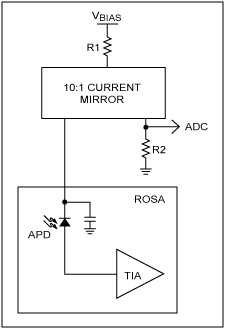
Figure 1. Schematic diagram of a typical APD current monitor
The current flowing through the APD can be calculated by the formula: IAPD = PRX × M × η, where:
IAPD is the current in mA
PRX is the received power in mW
M is the APD avalanche gain coefficient η is the conversion efficiency in A / W
The conversion efficiency depends on structural factors, temperature and wavelength, and its typical value is in the range of 0.65 <η <0.95.
The APD gain can be obtained by biasing the APD close to its breakdown voltage VBR. The typical value of VBR is 20V to 80V, which is determined by the APD structure and operating temperature. The closer the APD bias is to its breakdown voltage, the greater the M value. When the APD is in avalanche mode, M is proportional to the voltages VBR and VAP applied to the APD, and their relationship is: M ∠√ (VBR / (VBR-VAPD)). The precise measurement of M is determined by the APD material type, gain, and other parameters. For a typical APD of 155Mbps to 40Gbps, M is usually set at: 3 <M <10, Figure 2 shows a typical APD gain curve. As can be seen from Figure 1, when the optical input power increases, by reducing the value of M, R1 can increase the dynamic range of APD. As the R1 current increases, the APD voltage decreases. As a result, the APD deviates from its breakdown voltage and reduces the value of M. The formula is: M ∠√ (VBR / (VBR-(VBIAS-IAPD × R1))). It should be noted that by substituting the above equation, it can be found that M depends only on itself: M ∠√ (VBR / (VBR-(VBRAS-PRX × M × η × R1))). Through a current mirror with a detection ratio of 10: 1, the voltage applied to the ADC (VADC) is calculated according to the following formula:
VADV = IAPD × (1/10) × R2 = PRX × M × η × (1/10) × R2
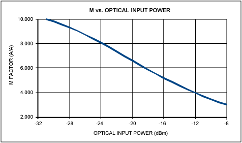
Figure 2. Typical APD gain curve
Enhanced RSSI Mode Overview The DS1864 SFP laser and diagnostic IC includes an enhanced RSSI mode for the MON3 channel, which is a differential input of a 13-bit ADC. The enhanced RSSI is also called dual-range feature. In the enhanced RSSI mode, the ADC will perform two different readings, called the precise reading mode and the rough reading mode (this mode is described on pages 20 and 21 of the DS1864 data sheet). Accurate measurement mode automatically measures small input signals. However, if the ADC inputs a large signal, the coarse measurement mode will be used automatically.
For APD RSSI measurements, it is important to note that the two ranges of enhanced RSSI have independent offset and span calibration factors. In addition, the precision measurement mode allows ADC measurement results to be shifted to the right by up to 7 bits. When configured for 7-bit right shift, the maximum reading in the precision mode is 01FFh, and the minimum reading in the coarse mode is 01E0h. To prevent the two ranges from overlapping (01FFh to 01E0h), a 31-bit hysteresis is provided.
APD RSSI dual-range calibration To meet SFF-8472, the monitoring circuit and ADC must be calibrated to ensure that 1 LSB = 0.1µW. Because M varies with input power, in order to keep each LSB at 0.1µW, the ADC step size needs to be optimized. If M changes from 3 to 10, using the LSB weighting of an ADC, the resulting total error is 10 × log10 (10/3) = 5.23dB. Because the DS1864 allows independent calibration of two different ADC ranges, two different LSB weights can be defined. This will reduce the error caused by the change of M. Figure 3 shows the ideal LSB weighting and two different weightings based on a typical APD and detector.
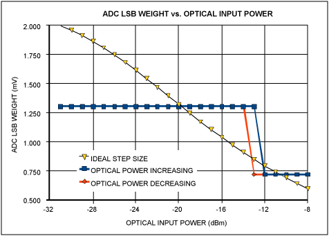
Figure 3. Ideal LSB weighting and actual calibration weighting for a typical APD detector
When the precise conversion configuration of MON3 is 7-bit right shift, LSB-weighted crossover occurs between the 1E0h and 1FFh steps of the ADC. The optimal LSB weighting value must be determined based on the APD and the monitoring circuit. The RSSI error obtained in the above example is shown in Figure 4.
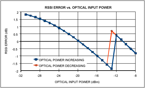
Figure 4. RSSI error in a typical APD monitor application
The unique acicular radiator,360 degree dissipation small wind resistance. High heat dissipation efficiency ensuring that the LED chip can work for 50000 hours.
Color temperature 3000-6000K
Light≥90LM/W
Matching the 2.3.4 lane,tunnel and Landscape Lamp,floodlight dedicated lens.Ensure that intensity and uniformity.
Glare index Signification reduce the original LED Module size,removal of power supply problems.Low demands for application situation and installation personnel More suitable for the transformation of traditional lamps.
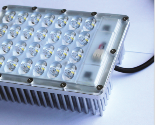
Technical parameters
Power :30W,30W,15W,15W
Structure size: 135×100×40 mm, 208×74×49 mm, 125×58×30mm, 380×40×25mm
Lens size: 135×100 mm, 186×64 mm, 125×58mm, 355×40mm
Input voltage: 220 V, 220 V ,220 V, 220 V
Input current: 0.132 A, 0.132 A ,0.123 A, 0.125 A
Luminous flux: 2760 LM ,2400 LM ,1230 LM ,1300 LM
Light effect: 92 LM/W 80 LM/W 82 LM/W 86 LM/W
Color temperature: 5000 K 5000 K 5000 K 5000 K
Power factor: 0.99 PF 0.98 PF 0.98 PF 0.99 PF
Working temperature: -40+50°C, -40+50°C, -40+50°C ,-40+50°C
Led Module,Led Modules For Signs,Led Module Bulb,Led Modules For Signage
Jiangsu chengxu Electric Group Co., Ltd , http://www.chengxulighting.com