In the past decade, automotive electronics has developed rapidly. Many of the functions that have been implemented with motors have been converted into electronic modules. The best example is the door device. Power windows, power mirrors and door locks controlled and driven by electronic control units (ECUs) are almost standard on all new cars.
This article refers to the address: http://
In a broad sense, electronic door systems have two different architectures. The first is a lumped system, usually with a central module that controls and drives each load in all doors. The second is a distributed system whose door function is implemented in multiple ECUs.
Although the lumped architecture is still used in some models due to its low cost, it is being phased out because: 1) The central module method requires a large amount of direct wiring, which increases the weight, wiring cost and cable short circuit. Risk; 2) A single module has limited functionality and cannot embed all required functions, such as comprehensive protection, diagnostics, and communication interfaces; 3) large-sized modules are difficult to assemble. These shortcomings have led to the rapid development of the system architecture of electronic doors.
There are currently two standard automotive protocols for connecting distributed ECU modules, namely CAN and LIN. Some major door functions can be implemented in different ways via the CAN/LIN interface. The most popular of these is the "door area module" or simply the "door module" method. In this approach, some of the main door function modules, such as door locks, mirrors, window lifters, and auxiliary lighting, are controlled and driven by separate ECUs.
The load characteristics and functions in the door module vary widely. The challenge for system designers is how to efficiently drive all loads while meeting design specification requirements and cost targets.
As the world's leading supplier of automotive semiconductor components, Infineon Technologies offers a full range of products that enable different drive strategies for different loads of door modules. This article describes the characteristics of these loads and the corresponding drive strategies.
System partitioning and main load of the door module
The door module is usually composed of three main functional modules: 1) a microcontroller; 2) basic functional modules including power supply, CAN/LAN communication, and circuits for performing external event monitoring and signal detection; 3) external load Connected drivers and power circuits. The typical system division of the door module is shown in Figure 1.
The load types of the door modules include DC motors, lamps, LEDs, and heating coils. Figure 1 also shows some of their characteristics. In order to efficiently drive these different functions and types of loads, different drive strategies are required.

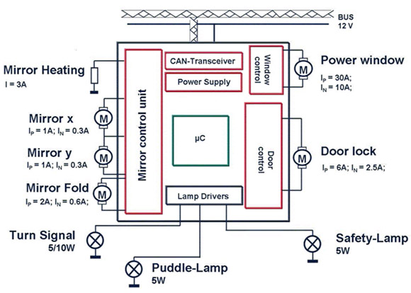
Figure 1: System partitioning and load characteristics.
Large load drive strategy: relay or smart device?
For large loads such as window-lifting motors, there are usually two different driving methods: the first is a relay-based method and the second is a semiconductor device.
The strategy of using relays is still widely used, mainly due to the low hardware cost, mature technology and good handling of large currents. However, this strategy also has many shortcomings known to everyone:
1. Relay solutions require more external components to form basic circuits such as fuses, pre-drivers (typically a pair of Darlingtons) and flywheel diodes;
2. The relay does not provide any protection for itself and the complete machine;
3. The relay itself does not have any diagnostic functions. It requires external components such as shunt resistors and op amps to achieve current monitoring;
4. The relay solution cannot implement PWM control;
5. Usually the relay itself is relatively large and requires a fuse box;
6. As a moving part, the mechanical reliability of the relay is low;
7. When the number of switching times is required (such as the application of a turn signal), the electronic life of the relay is very limited;
8. Fuse and relay solutions generate more heat because of the large power loss of the relay coils and contacts as well as the fuse itself and the shunt resistor.
The emergence of intelligent switches and bridges opened the door to solving the above problems. Some new devices, such as Infineon's NovalithIC, offer the right solution for high current motor drive designs.
The BTS7960 is the first member of the NovalithIC fully integrated high current half-bridge family of products. It contains three independent chips in a TO-263 package: a p-channel MOSFET as its high-side substrate and an n-channel. The MOSFET has its low-side substrate and a driver chip. The three chips are mounted in a common lead-frame using chip-on-chip and chip-by-chip techniques.
The BTS7960's path, RDS(ON), is 17 milliohms at 25°C. Its p-channel and n-channel MOSFETs are fabricated in different processes, ensuring fast switching of the high-side and low-side switches and avoiding crossovers. Current. This design differs from most bridges that use a charge pump with a limited maximum switching frequency, thus helping to implement high-frequency PWM control schemes and new features such as “soft†on/off windows with good EMI performance.
The driver IC is directly connected to the microcontroller for comprehensive protection and diagnostics. Protection features include current limiting, undervoltage/overvoltage blocking, overtemperature and full short circuit protection. Diagnostic functions include fault status flags and current monitoring, which are often required to implement pinch-off strategies. Some special features such as integrated dead time generation are also integrated to aid Dc Motor drive.
The BTS7960 is therefore an excellent replacement for relay solutions in protected high current motor drive applications in door modules. A typical application circuit for driving a large load such as a window lift motor with a BTS7960 is shown in Figure 2.
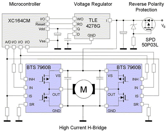
Figure 2: A typical application circuit for the BTS7960.
Small load drive strategy: ASSP or standard chip?
There are generally two ways to drive small loads, such as mirror motors, lights, LEDs, mirror heating coils, and even door-locking motors. The first method is to use a dedicated power ASSP, and the second method is to use a discrete standard device.
The aggregation of various requirements and the strong need to reduce system costs have made the platform concept increasingly popular in applications such as door modules. To meet this need, a highly integrated power ASSP is ideal. This device provides an excellent solution that not only saves PCB area and placement equipment costs, but also improves system quality and yield. At the same time, its huge output can also effectively reduce unit costs, further promote the development of such ASSPs, and enable them to be successfully commercialized. In addition, advanced semiconductor technology ensures that ASSP can be developed and manufactured in a reliable and cost-effective manner. The TLE8201R is such a power ASSP for door module applications.
The TLE8201R contains the power circuitry necessary to drive the smaller loads in a typical front door system, including door locks, mirror folding and adjustment motors, mirror heating and four 5W lights (such as turn signals, safety lights) , rear view mirror light or control panel light). The TLE8201R is a monolithic integrated circuit fabricated using Infineon's latest SPT6 technology, which combines hybrid technology with advanced high-power copper plating and side DMOS processes. This technology has lower on-resistance, higher current capacity, and greater repeatable clamp robustness.
Another important feature of the TLE8201R is the embedded standard serial peripheral interface (SPI). SPI not only saves the number of I/O pins of the microcontroller, but also has the flexibility to control the power circuit and quickly perform detailed fault diagnosis through error flags. This diagnostic function includes overload or load open detection for each individual channel, temperature warning and current sense output for the entire device. There are also various protection features such as short circuit and over temperature protection. Two direct PWM channels can be used to implement functions such as "soft" start/stop mirror heating, theater lighting effects for interior lighting, or compensation for LED brightness levels in control panel backlight applications. The DSO-36 package includes a full-size heat sink with low thermal resistance to ensure proper operation of the module under normal or even worst conditions. Figure 3 shows an example of a door module design using the TLE8201R.
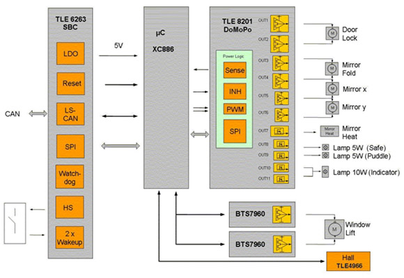
Figure 3: Block diagram of a complete door module with the TLE8201R.
Multiple standard chip solutions are more flexible in system configuration than door module dedicated power ASSPs, especially when some loads (such as mirror folding) are not needed. Designers are more free to choose the individual drivers that exactly match each load characteristic. These drivers can be relay-based devices or smart devices.
For motor applications related to rearview mirrors, devices such as the TLE6208-3G offer a cost-effective solution. It is a fully protected three-band half-bridge driver with SPI in a small SO-14 package. Since the half bridge has three possible states (high, low and tri-state), the two mirror position adjustment motors can be connected to the outputs of the three half bridges in a cascade configuration. The three-state function of the motor half-bridge saves a complete half-bridge driver. Operating modes such as forward, reverse, brake and high impedance can be controlled by the SPI interface. Diagnostic information from the bridge arm can also be output via SPI feedback. An example of a mirror motor drive using two TLE6208-3s is shown in Figure 4.
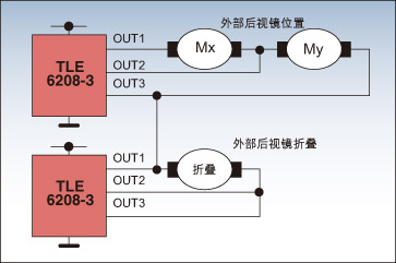
Figure 4: Example of a mirror motor drive using the TLE6208-3.
Compared to window lift motors, door lock motors are much smaller in size and current. Infineon's BTS7741 is fully compliant with design requirements and is an ideal replacement for relay solutions.
The BTS7741 is part of the TrilithIC family and consists of three dies in one package, including a double-pole high-side switch and two low-side switches in the SO-28 package. The high side switch is fully protected and includes control and diagnostic circuitry. The low side switch is also fully protected. In addition, the device has a load open detection function in power down mode.
The TrilithIC product line offers users more choices, and they can choose the right device that truly meets the technical and budget requirements. For example, if the load open circuit detection function is not required, the BTS7740 can be used. If the low side switch protection is not as strict, consider the BTS7700.
The mirror heating coils and lights in the door module can be switched with intelligent high side switches. Some devices in the Infineon PROFET family, such as the BSP772T, are well suited for this application.
PROFET devices include vertical-structured n-channel power transistors, charge pumps for high-end operation, and logic to perform various protection and diagnostic functions. Its PWM function can be used to achieve the "soft" start/stop of the mirror heater or special effects in the lighting control.
Figure 5 is an example of a door module in which a windowed motor is driven by a semiconductor device to drive other small loads with discrete standard components.
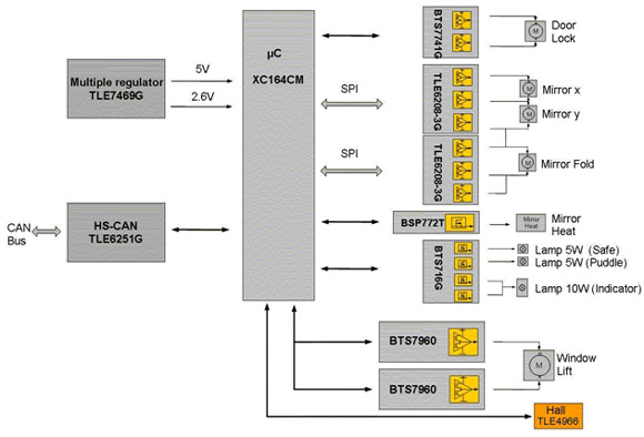
Figure 5: Block diagram of a complete door module with discrete components.
Summary of this article
From a few milliamps of LEDs to a window lifter of around 30A, different loads under the control of a typical door module ECU require different drive strategies. Large loads such as window lift motors can be driven with relay and fuse solutions, but a better solution is to use smart semiconductor devices such as the BTS7960, which provide more protection and lossless current monitoring in addition to the switching function. ASSPs that integrate a variety of door load drivers (such as the TLE8201R) are ideal for very compact PCBs. For basic door modules with only a small amount of load, the discrete smart device solution is the best compromise between cost optimization and flexibility to handle different requirements.
12V
dc motor Can drive under the rated voltage 12 v dc motor, most of the products our company can achieve the 12 v voltage drive, speed can be customized according to customer demand.
Characteristics: 12V dc
motor With torque, low noise, small size, light weight, easy to use, constant speed operation, etc, also can match all kinds of reducer in order to achieve the purpose of changing the output speed and torque
Application field: 12V Dc Motor part of the armature iron core, armature, commutator and other devices, dc motor is suitable for most of the electronic products, such as electric toothbrush, razor, medical apparatus and instruments, breeze machine, mixer, etc


Method of use: the best stable in horizontal plane, installed on the 12V Dc Motor output shaft parts, cannot use a hammer to knock, knock prone to press into the 12V dc motor drive, may cause damage to internal components, and cannot be used in the case of blocked.

Operating temperature range:
12V dc motor should be used at a temperature of -10~60℃.
The figures stated in the catalog specifications are based on use at ordinary room temperature catalog specifications re based on use at ordinary room temperature (approximately20~25℃.
If a 12V dc motor is used outside the prescribed temperature range,the grease on the gearhead area will become unable to function normally and the motor will become unable to start.Depending on the temperature conditions ,it may be possible to deal with them by changing the grease of the motor's parts.Please feel free to consult with us about this.


Storage temperature range:
12V dc motor should be stored ta a temperature of -15~65℃.
In case of storage outside this range,the grease on the gearhead area will become unable to function normally and the motor will become unable to start.
Service life:
The longevity of geared motors is greatly affected by the load conditions , the mode of operation,the environment of use ,etc.Therefore,it is necessary to check the conditions under which the product will actually be used .The following conditions will have a negative effect on longevity.Please consult with us should any of them apply.
â—Use with a load that exceeds the rated torque
â—Frequent starting
â—Momentary reversals of turning direction
â—Impact loads
â—Long-term continuous operation
â—Forced turning using the output shaft
â—Use in which the permitted overhang load or the permitted thrust load is exceeded
â—A pulse drive ,e.g.,a short break,counter electromotive force,PWM control
â—Use of a voltage that is nonstandard as regards the rated voltage
â—Use outside the prescribed temperature or relative-humidity range,or in a special environment.
â—Please consult with us about these or any other conditions of use that may apply,so that we can be sure that you select the most appropriate model.
when it come to volume production,we're a major player as well .each month,we rurn out 600000 units,all of which are compliant with the rohs directive.Have any questions or special needed, please contact us, we have the engineer group and best sales department to service to you Looking forward to your inquiry. Welcome to our factory.

12V Dc Motor
12V Dc Motor,Dc Motor 12V,12 Volt Dc Motor,Low Rpm Dc Motor
Shenzhen Shunchang Motor Co., LTD. , https://www.scgearmotor.com