Design of Network Interface of Remote Monitoring System of Test Station
The remote monitoring system is widely used in industrial remote monitoring, intelligent buildings, security monitoring, and network home appliances. Through remote monitoring, technicians can easily control and master the operating status and various parameters of instruments and equipment without visiting the site, and use it conveniently Local rich software and hardware resources perform process control on remote objects.
Because the test data is susceptible to electromagnetic interference and attenuation during the transmission of the wire, especially the data measurement of the equipment in the moving state or the equipment in the isolated area, it is very inconvenient to lay the signal transmission line, and the installation and maintenance are more troublesome. In response to this situation, we have designed a new type of wireless data transmission network interface solution that can overcome the disadvantages of traditional wired data transmission.
plan selection
1 Basic requirements for signal transmission of remote monitoring systems
Large-scale test stations are mostly automatic test systems, and their test parameters are measured by various transmitters, converters and measuring instruments. Some data needs to be monitored on site, but most of the measurement data needs to be transmitted to the test room. The test personnel monitor and process, analyze the waveform, draw characteristic curves and generate reports. In general, the signal transmission has the following requirements.
â— The transmission data channel and accuracy meet the test standard requirements.
â— Fast transmission response speed.
â— Stable operation and high reliability.
â— It can realize network information management.
2 Status analysis and plan determination
Based on the above requirements, the wireless transmission methods currently available at home and abroad are as follows.
â— Remote monitoring scheme for digital radio: it can use coding to complete soft or hardware spread spectrum to meet the requirements of data transmission, but the system cost is relatively expensive; the reliability of data transmission is low; maintenance is difficult.
â— Remote monitoring solution based on CDPD network: In the simple redevelopment application, the cost of the hardware part of the product is too high; the coverage is too small to be applied to the remote areas where the test station may exist.
â— GSM-SMS module-based wireless data monitoring system solution: It has many advantages such as wide network coverage, small user comprehensive investment, low operating costs, safe and reliable data transmission, etc. It is used to solve the problem of scattered monitoring collection points, wide coverage, mobile monitoring points, and real-time The monitoring and acquisition system with lower requirements has unparalleled advantages, but it is greatly affected by the opening of public network services and signal coverage, and by the operation of the system and network, uncontrollable factors are relatively large.
We propose a single-chip network interface of the monitoring system based on the combination of wireless data transmission and Ethernet network, extending the intelligent control unit in the monitoring system to the network, and embedding the TCP / IP protocol single-chip data communication system, so that the tester can pass the network The host or the Internet understands and controls the remote device. Based on TCP / IP protocol and STC89C5x series MCU and C51 development environment, the system and program framework are designed, using TCP, IP and simple application layer protocol in TCP / IP protocol to realize between MCU and between MCU and PC Network interconnection. This not only improves the speed of data transmission, but also ensures the correctness of the transmission, while also expanding the effective radius of data transmission.
The composition of the network interface
The controller of the wireless transmission system network interface adopts 8-bit microcontroller + streamlined TCP / IP protocol stack solution. The overall scheme structure is shown in Figure 1.
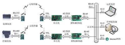
Figure 1 The overall scheme of the wireless transmission system network interface
The instrument or control equipment is connected to the wireless transmission module through the RS232 / RS485 interface, and transmits and receives data. The other end of the wireless transmission is connected to the single-chip microcomputer via TTL, and the single-chip microcomputer is connected to the RTL8019AS through the 8-bit data bus. The network controller is connected to the Ethernet through the RJ45 interface. Through wireless transmission and Ethernet, the instrument or control device and the remote monitoring host or the Internet have established a network connection, and the monitoring software on the remote host can be used to read the data of the instrument and meter to understand the working status of the control device and based on the collected data Perform analysis and control of field devices.
System composition
In the industrial measurement and control system, the field data measured by various instruments and meters are sent wirelessly through the wireless transmission device, and the data is wirelessly received on the monitoring host (PC) side through the wireless transmission device, and the data is recorded, analyzed, and stored to achieve information management .
The wireless transmission device at the instrument and meter end receives the command data frame sent from the PC, and wirelessly transmits the electricity and non-electricity data read from the instrument and meter. The wireless transmission device at the monitoring host end receives the data or parameters sent from the instrument and meter end, and sends the read data, parameter or write parameter command.
1 Hardware interface circuit design
The design of the network interface uses STC89C52RC to control the Ethernet chip RTL8019AS for data transmission.
â‘ The working mode of RTL8019AS
RTL8019AS supports three working modes: the first is the jumper mode, the I / O base address and interruption are determined by the jumper; the second is the plug and play mode, and the corresponding parameters are automatically configured by the software; the third is free Jumper mode, I / O and interrupt are determined by the content of the external 93C46.
The working mode of RTL8019AS is determined by the 65th pin JP, JP is the input pin, when it is low level (the same is true for other pins, the level of the floating input pin is low level, there is a 100kΩ Pull-down resistor), RTL8019AS works in the second and third modes, you need to use the 93C46 chip; when JP is connected to a high level (connected to Vcc or pulled up through a 10kΩ resistor), RTL8019AS works in the first mode , No need to use 93C46. The commonly used computers generally use the plug-and-play method and the jumper-free method, but the peripherals of this design are not frequently plugged and unplugged, so they do not support the plug-and-play function, and the 93C46 is not used to store the Ethernet controller parameters (by It is set when the microprocessor is initialized), but it uses an easy-to-control jumper. At this time, the address of the chip is determined by several pins of 85, 84, 82, 81 (IOS3 ... IOS0), as shown in Table 1.
Table 1 I / O base address selection

In this system, set IS03 ... IS00 to 0000, and the corresponding I / O Base is 300H.
â‘¡ RTL8019AS network interface
The network interface type of RTL8019AS is determined by PL0 and PL1 pins, as shown in Table 2.
Table 2 Network media selection
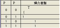
In this design, PL1 = 0 and PL0 = 0 are used, which is the first automatic detection method. RTL8019AS will automatically detect whether the medium is coaxial cable or twisted pair.
The interface between RTL8019AS and Ethernet adopts unshielded twisted pair RJ45 interface, and a network isolation transformer, also called transmit / receive filter, is needed in the middle, which is used to transform the signal into balanced signal transmission and prevent surges to reduce common mode. Interference, improve transmission efficiency.
The isolation transformer used in this design is 20F001N of GROUP TEK. In the specific connection, the signal ground wire should be connected to the power ground through a 10nF capacitor. A 200Ω resistor must be added to the output port of 20F001N to suppress the input voltage of 8019AS, which is also a protective measure.
The peripheral wiring of the Ethernet controller also includes the connection of the RJ45 interface and the LED indicator. The specific connection schematic is shown in Figure 2.
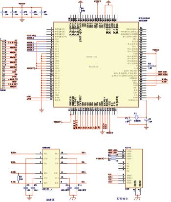
Figure 2 Schematic diagram of the peripheral circuit of the Ethernet chip RTL8019AS
â‘¢ Connection of single chip microcomputer and RTL8019AS
In this design, the jumper method is used. Connect 65 foot JP to a high level. After the system is powered on and reset, on the falling edge of RSTDRV, 8019AS will read the status of each jumper pin and write it into the system configuration register as the system default. Initial configuration.
The connection of each jumper pin: RQS0 ~ IRQS2 (78-80 feet) is the interrupt port. The query method is used in this design, so the choice of interrupt port has no effect; IOS0 ~ IOS3 (81, 82, 84, 85) are I / O base address selection, used to select the start address of the I / O port. To make it all low, the start address starts from 300H, and the address bus connection must be consistent with this; PL0, PL1 (74, 77 Pin) for network media type selection, set to "00" in this system, which means connection detection; BS0 ~ BS4 (pins 67, 69, 71, 72) are used for BROM capacity and base address selection, BROM is not connected in this system As long as BS4 and BS3 are set to low level, BROM can be disabled.
It can be seen from the above that all jumper pins are all configured to be low level. There is a 100kΩ pull-down resistor inside the chip pin, so when the pin is floating, it defaults to low level by itself, so these pins can also be left floating, and you should pay attention to these jumpers in related circuit design and software design. The pin configuration is consistent.
Data and address bus connection: Using 8-bit data bus, connect 96-pin IOCS16B to 27kΩ pull-down resistor to make 8019AS work in 8-bit data bus mode. The system data bus is connected to SD0 ~ SD7. 8019AS internal registers and memory read and write addresses are 00H ~ 1FH, only need 5 address lines to select. However, the start address has been set to 300H in the system jumper configuration, so when address strobe, the address lines SA8 and SA9 must also be set to "1".
Others include the connection to the crystal, as well as the power and ground connections.
2 Overall design of TCP / IP protocol stack
The ultimate goal of the network is to achieve data communication between any two points on the network node, but it is impossible to design a complete, comprehensive protocol that is effective for all possible communication modes, so the communication problem is divided Into small blocks, and design separate protocols for each small block, which makes each protocol easy to design, analyze, execute, and test. On the one hand, each protocol should deal with the communication problems not dealt with by other protocols to avoid duplication of work. On the other hand, the designed protocol should be able to share data structures and information to improve execution efficiency. Of course, the most important thing is that each protocol can work well together. Each protocol cannot be designed as an isolated protocol. This requires that they be designed as a system that supports and complements each other. Each protocol in the system solves Part of the communication problem, and all the protocols can solve all possible network communication problems.
The network interface of this system uses an Ethernet interface, so the protocol stack is designed following the TCP / IP model. Considering the extremely limited program space of the system, the standard protocol stack was simplified during the design. By selecting the appropriate protocol, the demand for processor hardware resources can be reduced. For example, due to high reliability requirements, you can choose to use only the TCP protocol instead of the unreliable UDP protocol. In addition, the protocol that has been selected for use has been appropriately simplified in specific implementation, and the necessary parts must be retained to save program space and execution time. At the same time ensure the reliability and security of the system, follow the layered design idea and modular design method, each protocol is implemented by the corresponding module, the module provides external interface functions for the main program to call, the simplified TCP / IP protocol stack is shown in Figure 3 Show.

Figure 3 TCP / IP protocol stack
The network interface layer is the bottom layer of the TCP / IP model, and the basic functions are completed by the RTL8019AS driver. The driver of RTL8019AS is responsible for encapsulating the data transmitted from the microcontroller to the Internet into the format of Ethernet data packets, and analyzing the data packets uploaded from the network to enter the upper layer protocol handler.
The functions of the network layer are completed by the ARP (Address Resolution Protocol), IP (Internet Protocol) and ICMP (Internet Control Message Protocol) protocols. The ARP protocol can determine whether the destination address in the data frame is the same as the local IP address, and if it is the same, receive the data frame, otherwise discard the data frame. IP is the core protocol of the TCP / IP protocol stack. All data at the network and transport layers are transmitted in the format of IP datagrams. ICMP allows hosts or routers to report error conditions and provide reports on abnormal conditions.

Figure 4 Data encapsulation process
The system needs to transmit the data by adding header information at each protocol layer, and finally encapsulated into an Ethernet data packet, which is transmitted on the physical network. The data encapsulation process is shown in Figure 4.
in conclusion
For the field of industrial control, the embedded Internet equipment interconnects the measurement and control network with the Internet, thereby realizing the unification of the measurement and control network and the information network. In a network composed in this way, traditional instruments and equipment act as independent nodes in the network, and information can be transmitted across the network to any field, and real-time, dynamic (including remote) online measurement and control become a reality.
Coupletech Co., Ltd. is professional manufacturer of Polarization Optics: PBS, NPBS and all kinds of polarizer and waveplate. Our Polarizing Optic products consist of Beam-splitting cuble, Polarizing Beam Splitter Cubes ( PBS ), Non-Polarizing Beamsplitter Cube ( NPBS ), Low order waveplate, Zero order waveplate, Dual wavelength waveplate, achromatic waveplate, Rochon Polarizer, Wollaston Polarizer, Glan Thompson Polarizer, Glan Laser Polarizer, Glan Taylor Polarizer, depolarizer, Brewster window, quartz, Polarization Rotator, optical isolator, and so on. Besides, we also supply optical coating, e.g. AR coating, HR coating, coating and wide range coating.
Coupletech is a long-term partner you can count on, especially polarizing optic. We focus on high quality, quick response, improving Ceaselessly, customer satisfying.


Polarizing Optic
Polarizing Optic,Polarization Rotator,Polarizing Filter,Circular Polarizer Filter
Coupletech Co., Ltd. , https://www.coupletech.com