Design of Central Door Lock Control Based on XC164CS and BTS7741G
Nowadays, more and more cars have adopted electronic door control system, and the central door lock is an important part of the door control system. This article combines the project practice of the door control module design, highlights the hardware and software design of the central door lock part, analyzes the operating characteristics and fault detection characteristics of the intelligent power chip BTS7741G, and gives the experimental results.
The overall design of the door control module
With the development of semiconductor technology, automobile door control systems have developed. Due to the various drawbacks of traditional relay and fuse control methods, it is urgent to introduce new control methods to improve the status of door control. This design is based on a 16-bit embedded system Vehicle door control system solution.
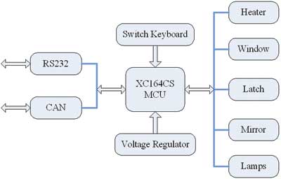
Figure 1 System structure block diagram
As shown in Figure 1, the door control module is mainly composed of the following parts: power supply circuit, power window drive circuit, rearview mirror drive circuit, heater drive circuit, central door lock drive circuit, lamp drive circuit, CAN bus interface Circuit, RS232 interface circuit and button interface circuit, etc. The microcontroller XC164CS is used to control the switching actions of all power devices, at the same time to monitor the system status regularly, provide appropriate feedback signals and periodically display diagnostic information, and realize information exchange through the vehicle network (such as CAN). Because the selected power device has provided perfect protection functions, this design avoids the use of too many power components, reduces the size of the module, and improves the electromagnetic compatibility of the module.
Central door lock control hardware design
1 The choice of smart power chip
Most of the existing central door locks adopt the relay driving method. However, the relay drive has many disadvantages: the drive current of the power relay excitation coil is large, it requires large power consumption and the interface circuit is complicated; the use of the relay increases the volume and weight of the controller; the switching frequency of the relay is relatively low, and the contacts are easy Jitter, it is difficult to meet the requirements of mechanical vibration when the vehicle is powered. In addition, contact jitter will affect the life of the relay, and the EMI is serious. It is difficult to effectively diagnose and protect the overheat, overvoltage, short circuit and other faults of the lamp. It needs to be used with a fuse to prevent overcurrent. However, once the fuse acts (that is, fuse), the circuit will be completely cut off, and the fuse needs to be replaced manually.
The intelligent power chip BTS7741G is suitable for the harsh application environment of automotive electronics. Its two high-side switches and two low-side switches have multiple intelligent protection functions such as undervoltage protection, short circuit protection to ground, short circuit protection to power supply, thermal shutdown and restart after cooling, and the two high side switches also contain faults The diagnosis circuit can diagnose the open circuit fault, short circuit fault and other fault states through the fault feedback pin ST, which is suitable for the control of the central door lock.
The BTS7741G contains four MOS tubes, two high-side switches and two low-side switches, which can be flexibly configured for output mode and can be used as an H-bridge or as a separate switch. The on-resistance of the high-side switch is 110mΩ, the on-resistance of the low-side switch is 100mΩ, and the working voltage can reach 40V.
2 Central door lock control drive circuit design
The connection circuit between BTS7741G and microcontroller is shown in Figure 2. BTS7741G is used as an H bridge to drive the central door lock forward or reverse. The driving process is controlled by time, and the motor runs for a certain time (the value of this design is 0.25s) to produce a certain displacement to achieve locking or unlocking. The motor running time is variable in the program. There is no active braking process, and motor braking is achieved through the freewheeling of the upper tube. There must be at least 0.5s time interval between the two central door lock switch actions to ensure that the MOS tube is reliably turned off.
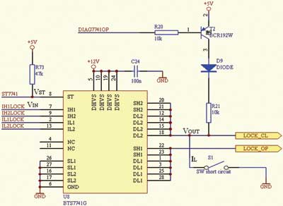
Figure 2 BTS7741G and microcontroller connection circuit
The state of the door lock is unknown after power-on, so the microcontroller first closes the door lock. The motor drive of the central door lock does not use PWM voltage regulation. SH2 is connected with a 1kΩ pull-up resistor and is powered by a + 12V power supply, which can realize open-circuit fault detection in the off state.
BTS7741G short circuit to ground experiment
Although the two high-side switches and two low-side switches of BTS7741G have complete short-circuit protection functions, the fault feedback pin ST can only feedback the short-circuit fault status of the two high-side switches. Therefore, this design did a short circuit test to the ground for the high-side switch of BTS7741G. The experiment is divided into two situations: short circuit first and then power on, and first power and then short circuit.
BTS7741G's short circuit to ground test conditions are + 12.45V battery voltage, + 5V power supply, 1.5m short circuit wire (R = 0.12Ω) As shown in Figure 3, where VST is the voltage from the ST pin to ground, VIN is the voltage from the IH1 pin to ground, VOUT is the voltage from the OUT pin to ground, and IL is the short circuit through the BTS7741G when a short circuit to ground fault occurs Current.
1 Short circuit to ground under short circuit and then power on
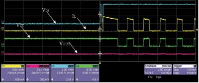
Figure 3 BTS7741G first short-circuit and then power-on short-circuit experiment waveform diagram first half
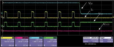
Figure 4 BTS7741G short-circuit first and then power-on short-circuit experiment waveform diagram second half
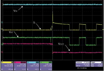
Figure 5 BTS7741G first power-up and short-circuit short-circuit experiment waveform diagram first half
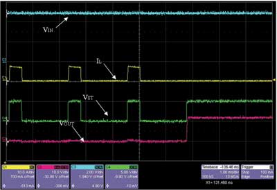
Figure 6 BTS7741G first power-on and then short-circuit short-circuit experiment waveform diagram second half
As shown in Figure 3, at the moment when the switch is pressed, a large number of burrs are caused by the switch's own mechanical structure; the instantaneous surge current is 10A (25 ℃, the typical value of the short-circuit current peak value of BTS7741G is 10A); the output voltage VOUT has been It is low level; ST fault diagnosis pin is pulled down about 1.4ms after the short circuit occurs, which means that BTS7741G diagnosed the fault at this time. After that, the BTS7741G will periodically turn off the MOS tube, so the short circuit current IL is periodically clamped to 0A, which effectively suppresses the continuous heating of the chip caused by the short circuit current, thereby protecting the chip from damage due to short circuit; the ST pin The level will be periodically pulled low as the short-circuit current changes. As shown in Figure 4, when the chip is completely cooled, the BTS7741G can be restarted and continue to work normally.
2 Short-circuit to ground test under the condition of first power-on and short-circuit
As shown in Figure 5, at the moment the switch is pressed, the instantaneous inrush current is 25A, which is much higher than the typical value of the short-circuit current peak value of 10A at 25 ° C for BTS7741G. But the inrush current of 25A only reduces to 10A immediately after less than 30μs, so the chip is not damaged much; the output voltage VOUT is pulled down to low level at the moment of short circuit; ST fault diagnosis pin after short circuit occurs Being pulled low about 1.6ms means that the BTS7741G has diagnosed a fault at this time. After that, the BTS7741G will periodically turn off the MOS tube, similar to the first short-circuit and then power-on short-circuit experiment. The short-circuit current IL is periodically clamped to 0A, and the level of the ST pin also periodically changes with the short-circuit current. Is pulled low. As shown in Figure 6, when the short-circuit phenomenon disappears, the BTS7741G can be restarted, the output voltage VOUT is high level, the chip is not affected by the short-circuit condition, and continues to work normally, which fully shows the perfect short-circuit protection function of the BTS7741G.
Software design of door lock
The algorithm of the door lock software is to control the appropriate bridge arm to be turned on or off in the appropriate state. When the door lock is opened or closed, the upper and lower bridge arms need to be turned on. After opening or closing, the freewheeling needs to be performed. At this time, only the lower bridge arm needs to be turned off, and the upper bridge arm can be turned on for a period of time. The specific control algorithm can refer to the state flow diagram of the door lock shown in FIG. 7.
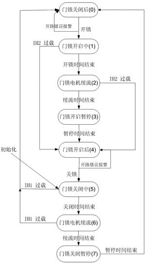
Figure 7 Flow chart of door lock control state
Table 1 gives several working states of the door lock.

The transition between various working states is not triggered by the control command ubCmdLatch. The two conversions from LATCH_CLOSED to LATCH_OPENING and from LATCH_OPENED to LATCH_CLOSING are triggered by ubCmdLatch, which means that after the command to open or close, the door lock starts to change from a static state to a moving state, that is, the door lock The closed static state starts to open, or starts to close after being opened. In the PASSAT B5 electric car door, an electric door lock is used. The opening or closing of the door lock is achieved by the motor driving the lock latch forward and backward. The internal BTS7741G is a simple H-bridge circuit, so the H-bridge is controlled by the program to open the appropriate upper and lower bridge arms at the right time to achieve the purpose of controlling the positive and negative rotation of the door lock motor. In the two states of LATCH_OPENING and LATCH_CLOSING, commands to control the conduction of a pair of upper and lower bridge arms are written. In the states LATCH_CLOSED and LATCH_OPENED, none of the four tubes are conducting.
The rest of the transitions between the various states are not triggered by control commands, some are through timing, and some are through error detection. The fault detection function is realized by monitoring the output level of the ST pin. Under normal conditions, the ST pin outputs a high level; when a fault occurs, the ST pin outputs a low level. The specific state switching can be clearly seen from FIG. 7. For example, from the state LATCH_OPENING to LATCH_OPEN_FREE is to count to the end of the door lock open time (LATCH_OPENING_TIME), and if an open circuit fault or an overload fault is detected, the door lock will remain in the LATCH_CLOSED or LATCH_OPENED state.
Through the research and analysis of the working characteristics and fault detection characteristics of the intelligent power chip BTS7741G, the safety of the chip is affirmed, ensuring the correctness and reliability of the design.
modern led Crystal Ceiling Light, Cover with 304 stainless steel and Top K9 crystals. The light source is LED SMD or led spot light. The light will be cery shining. And it can use remote control or sensor, that is very convenient. There are many different patterns and designs for customer to choose.


Modern Crystal Ceiling Light,Crystal Modern Light,Modern Hanging Light,Crystal Ceiling Lamp
Zhongshan Laidi Lighting Co.,LTD , http://www.idealightgroup.com