Foreword
Limited by the implementation of base station antenna far field test time and cost, many mobile operators cannot test antennas as they wish. Because it takes a very long distance to build a far field, it is not suitable to test the far field directly in the full anechoic chamber. It is difficult to find an outdoor test base, and the use of outdoor bases is limited by weather factors. This requires specific rooms to be able to test large antennas using specific techniques. In addition, many base station antennas undergo mechanical adjustments that change the array mode, which requires a test method with multiple settings. Based on the above difficulties, testing in a full anechoic chamber costs at least $1,800 to $2,000 per day, and each test takes three to four days. If the test indicates that the design is to be improved, the mobile operator is likely to perform additional tests unless they have pre-tested before the full anechoic chamber test. The full anechoic chamber test was scheduled for two or three months, so scheduling the test alone delayed the project release by quite a bit.
To overcome these difficulties, engineers at a large mobile operator used the EMSCAN RFX2 antenna model test system. The desktop scanner generates antenna test data and maps the results to the far field model. In this case, the test group was tested in 700 MHz and 1950 MHz environments. Since the array size exceeds the range that the scanner can scan, the test group cannot test the antenna once. To solve this problem, they performed four scans, scanning every 40 cm, to form a total scan area of ​​160 cm * 40 cm.
Test setup
Note that the antenna array in Figure 1 is suspended above the RFX2 scanner at a maximum supportable distance of 115 mm to minimize the effects between the scanner and the antenna under test. The measured antenna array weighs 20kg, is 150cm long, 30cm wide and 15cm thick. The first test position RFX2 in Figure 1 below is close to the top of the antenna array. The absorbing material covering the scanner also helps to minimize the effects of manually moving the scanner down to a 40 cm position. This movement of the scanner corresponds to the scanning range of the scanner. During the test, when the engineers manually scanned the scanner to the next position, they monitored the antenna's S11 with the aid of a network analyzer. The absorbing material works as expected, with little change in return loss as the scanner moves. After the first scanner has measured the first segment, the scanner is moved 40 cm to the left and tested by the second scanner with no other changes. Each scan takes less than 2 seconds, and the test group does not move the scanner to the next test position until the four scanners complete the scan. Each subsequent test overlaps with the previous scan area to form a calibration point that accurately connects the four scanners into a single line. The entire test and subsequent processing time takes about 30 minutes.
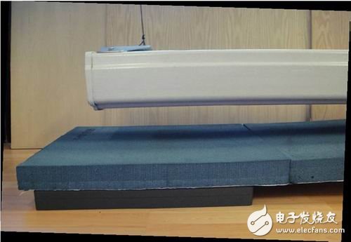
Figure 1: Test setup
Results at 700MHz
Using subsequent processing techniques, the test team combines the four images into one. Phase continuity is formed between the four test locations. Although the phase change was manually implemented in this study example, the phase continuity is automatic because of a small change in hardware development. Figure 2 shows the results of an electromagnetic field (H-field) combination using a very near-field test at 700 MHz. Each of the figures in the figure below lists Hx amplitude, Hy amplitude, Hx phase and Hy phase. The right side of each figure passes through the connector to correspond to the end of the antenna.
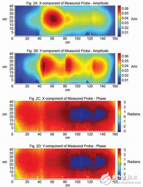
Figure 2: 700MHz electromagnetic field (H-Field)
Using post-processing techniques to convert near-field test results at 700 MHz into far-field results, then use a customized, patented program to convert them into far-field results while eliminating predictable coupling effects in the test array.
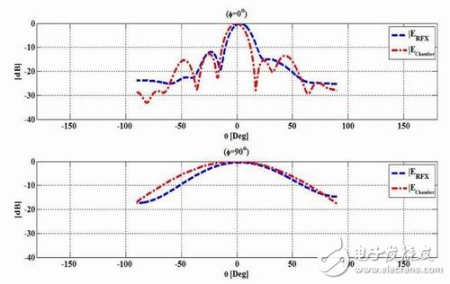
Figure 3: 700MHZ radiation pattern VS data in the product manual
Hand Blenders are small multi-function kitchen small appliances, including stick, chopper, egg whisk and measuring cup. They can mixing, chopping, and whisking eggs. Some customers need only hand blenders, some need Hand Blenders 2 In 1, and some need full set Hand Blenders 4 In 1.
Due to small in size, multi-fuction and competitive price, hand blenders are popular in home and abroad day to day. Weclomre to contact us for more information about them.

Hand Blenders
Hand Blenders,Immersion Blender,Stick Blender,Hand Held Blender
Flying Electronic Co., Ltd , https://www.flyingelectronic.com