3G base stations, whether CDMA2000 1x, EV-DO, WCDMA, or TD-SCDMA, use more complex wireless technologies, such as code division multiple access, complex modulation, and precise power control. TD-SCDMA also uses time-slot bursts and flexible link allocation. Its installation and maintenance testing work is more complicated, requiring new testing methods and testing tools. This article takes TD-SCDMA as an example to introduce the base station field test, most of the content is also applicable to other 3G systems.
The instrument that performs on-site testing of 3G base stations must have a comprehensive analysis function, capable of analyzing performance indicators in the frequency domain, time domain, code domain, and modulation domain. In addition, the portability and robustness of the meter need to be considered. Anritsu's MS272xB series of handheld spectrum analyzers and MT8222A / MT8221B base station comprehensive tester (Figure 1), which are based on years of successful experience in handheld instrument development, can fully meet the above test needs and support all 2G / 3G systems. The tests described in this article are based on the functions of the above instruments.
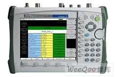
Figure 1: The powerful base station comprehensive tester MT8222A.
Based on the principle of convenience and reasonableness, the air interface measurement method should first be used to check the signal coverage and signal quality of the base station transmitter at the appropriate location, and strive to make an accurate judgment on the state of the base station in the air interface test. If it is difficult to judge the measurement results of the air interface or need to accurately measure the transmission power, you need to directly connect to the base station for testing. The test procedure is shown in Figure 2.
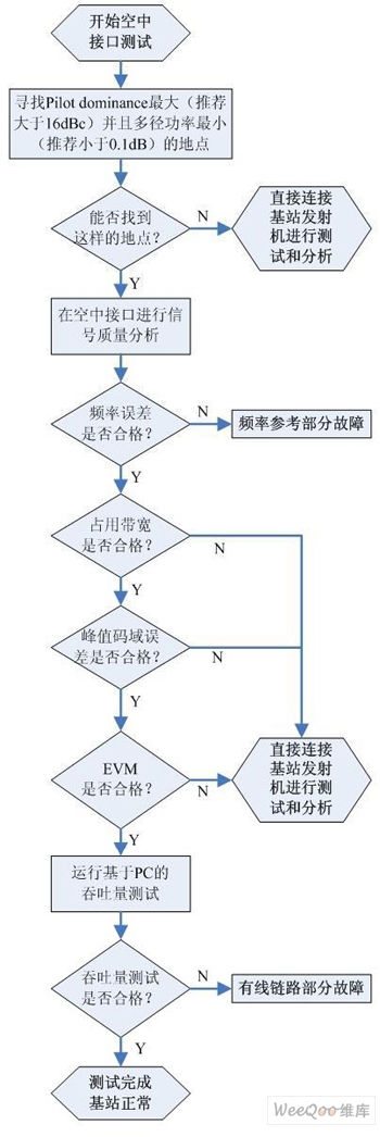
Figure 2: 3G base station test procedure.
In order to obtain stable and reliable air interface measurement results, a suitable measurement location must be found, which requires a high pilot advantage. It is generally required that the pilot advantage is greater than 10dB. The main test items and definitions are introduced below.
1. Base station coverage and co-channel interference testing

Figure 3: Base station coverage and co-channel interference test interface.
Synchronization code and pilot advantage: The synchronization code scan shows all active synchronization codes at the current location. Multiple strong sync codes will cause co-channel interference. It is required that the number of sync codes within 95% of the coverage area and the difference between the signal strength of the main sync code and within 10 dB should not exceed 3 Pilot advantage can help determine the appropriate air interface measurement location, generally requires greater than 10dB.
Downlink pilot time slot power: Downlink pilot time slot power can check coverage, and test data can also be downloaded to map software for analysis. It is required to be greater than -88dBm in 95% coverage area.
2. Multipath testing

Figure 4: Ec / Io and Tau test interface.
The two air interface test projects, Ec / Io and Tau, are used to help solve the coverage problem, and the six strongest synchronization codes can be tested simultaneously. If further details are required, scrambling code information will be given on the code domain power test interface.
Ec / Io: Measure the signal strength (signal-to-interference ratio) of the 6 strongest base station synchronization codes. It is required to be greater than -2dB in the 95% coverage area.
Tau: indicates the distance between the base station and the test site. The base station with the strongest synchronization code is required to be closest to the test location.
3. RF index test
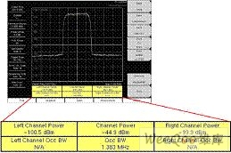
Figure 5: Test interface for channel power and occupied bandwidth.
The channel power determines the cell coverage area. A power change of 1.5 dB means that the coverage area changes by about 15%. The error between the test result and the rated value should not exceed ± 1.0dB. The base station should be directly connected for channel power measurement. The high-precision power meter option can provide a measurement accuracy of ± 0.16dB.
Occupied bandwidth measures the bandwidth occupied by 99% of the signal power, with a typical value between 1.3 and 1.6 MHz. More than 1.6 MHz means that it will cause interference to adjacent frequency points.
4. Slot power
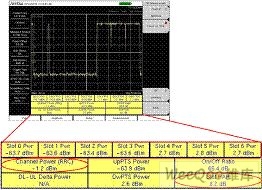
Figure 6: Test interface of downlink empty time slot power and time slot peak-to-average ratio.
Downlink empty slot power measurement can help determine the interference situation caused by the base station and the degree of self-interference with the uplink signal, because these measurements can reflect whether the base station transmitter can be fully turned off. The measurement result is required to be less than -82dBm (directly connected to the base station for measurement).
The peak-to-average ratio of the time slot refers to the ratio of the peak power and the average power of the time slot. If the peak-to-average ratio is too low, it is likely that the amplifier compresses the signal and will cause distortion. Typical values ​​should be greater than 6dB.
5. Signal quality test
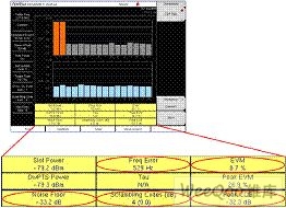
Figure 7: Error vector magnitude (EVM), peak code domain error, frequency error, noise floor level test interface.
EVM represents the proportion of error in the signal. The measurement result should be less than 12.5% ​​(directly connected to the base station test).
Peak code domain error refers to the error vector amplitude (in dB) of the worst code channel. This indicator is used to monitor the most severe signal distortion caused by channel board problems or amplifier compression. The measurement result should be less than -28dB (spreading factor is 16).
The frequency error is used to judge whether the carrier frequency of the base station is accurate. As long as the test instrument and GPS clock are synchronized together, the carrier frequency error can be accurately measured on the air interface. Index requirements: large area base station is less than ± 0.05ppm, cell base station is less than ± 0.1ppm
The noise floor level is a general measurement indicator of code domain signal quality. Any type of code domain modulation error will increase the noise floor level of the code domain. The measurement result is required to be less than -20dB.
Summary of this article
The 3G network requires a more comprehensive base station wireless performance test, and the test instrument needs to have the above measurement function to accurately judge the performance of the 3G base station and network. The full-featured high-performance handheld instrument is the best tool to complete the above test. This article only briefly discusses 3G base station testing. Anritsu has also prepared more comprehensive and detailed 3G base station test guides and system test solutions for users.
We are amongst the trusted manufacturer, supplier & exporter of premium quality range of Solar Led Street Lights.
These solar LED Street Lights are highly efficient and very economical systems for lightning different places. Our solar LED Street Lights are ideal for outdoor applications designed to efficiently harness solar power and store for use during night time.
We offer very robust, long lasting and very bright solar lighting systems to our clients at economical prices.
With the support of our skillful professionals, we offer our customers a high quality 12W LED Panel Light Square. Perfect for both indoor and outdoor purposes, offered square light is perfectly designed to meet the requirements of patrons.
120W Integrated Solar Street Lights
120W Integrated Solar Street Lights,120W Smart Solar Street Light,120W Solar Street Lights,120W Integrated Solar Street Lamp
Yangzhou Bright Solar Solutions Co., Ltd. , https://www.cnbrightsolar.com