Design and Application of CMOS Detector in Radiographic Testing
Overview: The digital ray detection technology with CMOS detector as the recording medium has high detection accuracy, good temperature adaptability and strong structure adaptability. The detection units of the CMOS ray scanning detector are arranged in a line array, and relative scanning movement needs to be performed during the detection, and line-by-line collection and stitching into a complete transillumination projection image. The design of inspection tooling is introduced, and the fixing, position adjustment and relative movement of the detector and the inspection workpiece are completed. The configuration and calibration of detectors, the selection of transillumination methods, the control of movement speed, the optimization of detection parameters, the quantitative analysis of defects, and the management of image archives are introduced. The application results show that, after process optimization, the CMOS detector can realize the radiation detection of most product parts. Finally, it analyzes the problems in the application and the follow-up research directions.
ApplicaTIon of Direct Radiography Using CMOS X-ray Linear Array Detector
SUN Chao-Ming, LI Qiang, WANG Zeng-Yong, LI Jian-Wen
(InsTItute of Machinery Manufacturing Technology, CAEP, Mian yang 621900, China)
Abstract: The digital radiography (DR) using complementary metal oxide silicon (CMOS) X-ray linear array detector as record media had advantages of higher spaTIal resoluTIon, better temperature adaptability and flexible structure adaptability. During radiographic testing, relative movement of the detector and the work piece was necessary to collect each line of the scanned image, as the detecting units were lined in a row. So the testing equipments were designed to mount the detector, adjust the relative position and move the work piece according to its structure. The testing procedure comprising configuration and calibration of the detector, selection of the applicable scan mode, control of the scan speed, optimizing of the testing parameters, segmentation and quantification of defects and archiving and retrieval of the digital images were described. After optimizing the testing process , it showed that CMOS detector had capability to achieve better images and it could be used in rad iographic testing widely. The benefit of using DR and some problems to be solved were talked in the end.
Keywords: Digital radiography; CMOS X-ray linear array detector; Process optimization
1 Brief introduction of CMOS detector The ray detection technology uses X-rays to detect discontinuities in the material and display images on the recording medium. With the continuous advancement of technology, the radiographic inspection has continuously expanded from the traditional photographic method using film as the recording medium, and various digital radiographic inspection methods have been formed, such as film digitizing technology (Film Digitisation) and real-time radiography imaging technology (Radioscopy) , Computerized Radiography (Computed Radiography) and Direct Digital Radiography (Direct Radiography) technology [1]. In practical applications, it is necessary to select an appropriate method according to the resolution and relative sensitivity required by the test. Compared with other ray recording media (such as CCD, polysilicon, etc.), CMOS (complementary metal silicon oxide) technology has more performance advantages. At present, the minimum pixel size of the CMOS detector can reach 39 μm, the detection accuracy is high, the temperature adaptability is good, and the structure adaptability is strong.
Compared with a large intensifier imaging system, the CMOS ray scanning detector (Figure 1) has a compact structure and high internal chip integration. Compared with the CCD imaging method, each detection point of CMOS has its own amplifier for individual configuration. CMOS converts the received rays into light through the conversion screen inside, and the detection point unit directly in contact with the conversion screen converts the light into electrons. Each detection point unit has its own amplifier to amplify the electrical signal, and finally in the detector A / D convert the signal to form a binary code and send it to the computer. CMOS is mainly suitable for 20-320 kV ray energy, 80 / μm spatial resolution, without geometric magnification, the detection resolution is 6 lp / mm, and the detection image reaches 4096 levels of gray.
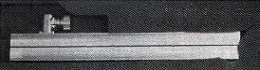
Figure 1 CMOS ray scanning detector
2 Detection application of CMOS detector
2.1 Detection process Because the CMOS ray detection units are arranged in a line array, only one line in the projection image formed by rays passing through the object under inspection can be obtained in a stationary state. In order to obtain the image of the detected object, it is necessary to perform a relative scanning motion, collect line by line and put together a complete projection image. When acquiring inspection images, it is required that the ray energy fluctuation is as small as possible and can work continuously for a long time, so the author uses a constant voltage ray source (YX-LON MG325, maximum voltage 320 kV, large focal point 3.0 mm, small focal point 2.0 mm). The process of ray detection using a CMOS linear X-ray scanning detector is as follows: detector configuration and calibration—determination of transillumination mode, adjustment of position parameters—relative motion, acquisition of scanned images—image processing, and defect analysis.
2.2 Design of inspection tooling The imaging unit (line array) of the detector needs to be well matched with the center line of the ray beam, and phenomena such as relative position tilt and offset cannot occur. Therefore, it is necessary to design appropriate imaging tooling to complete the fixing, position adjustment and relative movement of the detector and the detection workpiece. The tooling should be able to be easily moved in and out (cylindrical workpiece), and it should have certain flexibility and greater adaptability (detect different types of workpieces).
Based on the principle of simplicity and practicality, the inspection tooling design is carried out on the basis of the existing real-time imaging system, that is, the inspection workpiece is placed on the stage during the inspection, which can achieve left and right translation, rotation around the vertical axis, etc. The tooling is fixed on the motion axis of the intensifier of the real-time imaging system of the ray, which can realize vertical lifting and translation. In addition, the detector can also achieve a certain angle of rotation adjustment. Through the organic combination with the real-time imaging detection system, it can realize the radiation detection of various types of workpieces. In addition, a fixed positioning tooling must be designed for the workpiece during application.
2.3 Detector configuration and calibration When using the detector for the first time, you need to specify the imager type parameters (length and withstand voltage, etc.) in order to determine the minimum integration time available. Before the detector works normally, it must be configured and calibrated so that under certain imaging conditions, the offset output and gain output of all detection units are consistent.
For new detection objects, first configure the relevant parameters of the acquired image (integration time, scanning accuracy, and whether to add the average), and then start the detector calibration. When calibrating, the influence of focal length and object distance must also be considered. In general calibration, three steps are required: â‘ turn off the ray source, and the detector performs offset calibration. â‘¡Turn on the ray source, adjust to the current and voltage value required for detection, so that the output signal of the line array of the detector reaches the maximum but there is no saturation. â‘¢ Adjust the ray energy to reduce the output signal of the line array to half of the maximum signal. The calibration result is stored in the form of a file, which can be used for later detection and calling. However, if the calibration parameters are changed again after the call, re-calibration is required before testing.
For most detection objects, the current and voltage values ​​used in actual detection are high, and the output signal is already saturated when the detector is calibrated. In order to solve this problem, according to the detection conditions of different thicknesses, corresponding test plates for calibration were designed. The thickness of the test plate is uniform. After the first step of the calibration is completed, place the test plate in the ray source window, and then turn on the ray for the next calibration operation.
2.4 Selection of transillumination mode (1) The translation mode is suitable for the radiographic inspection of flat welded workpieces. During the inspection, the detector and the ray source are kept relatively fixed, and the workpiece is placed on the stage, along the X axis at a suitable speed parallel movement. For circular welds on tubes and cylinders, if translational imaging is used, the elliptical perspective image will be collected. Only the image in the central area can be used for evaluation of the test results, and it needs to rotate multiple angles to complete all the tests. In order to improve the detection sensitivity (Figure 2a), in some cases, the transillumination detection cannot be achieved because the thickness is too large.
(2) The rotation method requires the relative position to be adjusted so that the workpiece is placed in the center of rotation of the stage, and is in a straight line with the center of the beam and the center of the detector. For cylindrical parts, the detector is placed inside the workpiece through tooling, as close as possible to the detection site, and single-wall single-shot is used for transillumination; for tubular and cylindrical workpieces with small inner diameters, double-wall transillumination is used; Rotating a certain angle can expand the transilluminated area and image it, which can effectively improve the detection efficiency (Figure 2b). For rotary workpieces, the use of rotating imaging has outstanding advantages, which can improve image quality and shorten inspection time.
2.5 Motion speed control Because the detector must have relative motion to be imaged, the motion speed needs to be controlled within a reasonable range. If the speed is not suitable, the resulting image will be stretched or compressed. In addition, the higher the resolution and the lower the image noise, the lower the motion speed.
|
|
(a) Translation mode | (b) Rotation method |
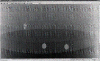
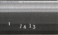
Figure 2 Detection images acquired by different transillumination methods
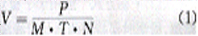
The moving speed V in translational imaging is related to the exposure time T of the detector, the imaging accuracy P, the transillumination magnification M and the number of repeated scans N:
For the rotation method, the inner diameter of the workpiece needs to be calculated.
2.6 Optimization of detection parameters The optimal magnification Mopt is related to the inherent unsharpness of the detector Us and the ray focal point size d [2]:
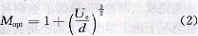
After calculation, the optimal magnification Mopt = 1, that is, the detector is as close as possible to the detected workpiece during imaging. In addition, the imaging quality is also related to the selected parameters such as transillumination voltage, current, focal length and focus.
The clarity of the scanned image is related to the number of repeated scans. The Double Graylevel option is used during image scanning, similar to the 4-frame image overlay in real-time imaging detection (N = 4). The speed of inspection is reduced by 4 times, but the image has been greatly improved, the noise is significantly reduced, and it is more conducive to the detection and recognition of defects. The detection image can meet the AB level requirements stipulated in the GB 3323-1987 standard.
2.7 Quantitative analysis of defects When performing image size measurement, it is necessary to measure the measured or known exact size test piece close to the side of the weld to be inspected and image the weld at the same time. Before each evaluation, a calibration should be made, and the defect size should be compared or the size of the image should be converted to the real size through the formula. To this end, a dedicated test piece for measuring evaluation (Figure 3) was designed. The test piece can also be used to detect whether the relative motion speed matches.

Figure 3 Test strip for quantitative analysis of defects
After the size calibration is completed, the quantitative analysis of defects is realized through image processing methods. Use Canny edge detection algorithm to locate the defect edge. Next, thinning is performed on the detected edges. Then, by searching the 5 × 5 or larger neighborhood centered on the end point of each edge line, find other end points and fill them, complete the edge point connection, and remove the gap in the edge detection image. Then apply the pixel marking method to check the connectivity of the adjacent points of each target pixel, and perform the target marking in the closed curve. Through the above operations, different defects can be marked for measurement, and finally the defect parameter calculation is completed [3].
2.8 Image archive management The test results are stored on the computer in the form of digital images. In order to facilitate the unified management of the test images, the author has designed an image file management database to record the test information (workpiece name, test date, etc.), imaging parameters and test Evaluation results, etc.
3. Application conclusion and problem analysis CMOS ray detector has high spatial resolution (61p / mm, inherent unsharpness <0.2 mm) and high detection sensitivity (4096 gray levels). The imaging quality is better than the real-time imaging system using an intensifier, which is close to or at the level of film photography; the image contrast is better than the film photography method and real-time imaging system.
Through test optimization and other methods, the detector has been successfully applied to the radiographic inspection of most product parts such as flat welds, girth welds and longitudinal welds, which improves the inspection efficiency and reduces the inspection cost. In order to better promote the application of digital ray detection technology, it is necessary to carry out research work in the following areas:
(1) Optimal detection and simulation of complex workpieces [4], providing theoretical support for the interpretation of test results.
(2) Research on the rapid reading, processing and analysis of large-capacity image files, and the automatic and semi-automatic methods for quantitative analysis of defects.
(3) Management and transmission of image files (introducing PACS mode) [5].
(4) Establish new digital radiographic testing standards.
references:
[1] Nedavnii OI, Udod V A. Digital radiographic systems today-state of the art (a review) [J]. Russian Journal of Nondestructive Testing, 2001,37 (8): 576-591.
[2] Zeng Xiangzhao. X-ray real n-inch imaging inspection image with the best magnification and minimum defect detection [J]. CT Theory and Application Research, 2002, (11): 13.
[3] Sun Chaoming. Segmentation and quantification of defects in digital radiographic inspection images [C]. Chongqing: 2006 Ninth NDT Academic Annual Conference in Southwest China and 2006 National Symposium on New Technology of Radiographic Testing, 2006.
[4] Sun Zhaoming, Wang Zengyong. Development of simulation technology in radiographic testing [J]. Nondestructive testing, 2006, 28 (9): 475-478.
[5] Zhang Jian, Chi Feng, Gao Xinbo, etc. Research on large-scale medical image distributed storage system based on DICOM standard [J]. Computer Application Research, 2004. (4): 85-87.
DC emergency standby power supply system consists of AC distribution, charging unit, storage battery DC distribution, automatic switching against city grid failed in power supply, etc. It is applied to provide uninterrupted power supply service for the important DC electricity loads.
AC emergency Backup Power Supply system, basing on DC standby power supply, is equipped with single phase (three-phase) DC/AV inverter. It is applied to provide uninterrupted single phase (three-phase) AC power supply service for the important AC electricity loads.
Emergency Power Supply,Led Emergency Power Supply,Emergency Battery Power Supply,Emergency Battery Operation Power Supply
Xinxiang Taihang Jiaxin Electric Tech Co., Ltd , https://www.chargers.be