Part 1: Installation and setup
OK! Let's get started! First, some important rules:
For front-projection projector settings, make your room as black as possible, preferably better to all black (just like when you are watching a movie), make sure there is no light on the screen. The same is true for this part of the notebook or computer screen. Keep them away from the screen and turn down the brightness of the notebook or computer screen.
Allow your projector/TV to warm up for at least 30 minutes before making grayscale corrections. It takes time to reach stability. Please note: If you are using a plasma display, make sure the sensor is on the display for at least 30 minutes because the plasma will heat up and you should stabilize the sensor to the same temperature.
Step 1.1: The software we use to measure grayscale is called ColorHCFR. The first step is to download and execute the ColorHCFR Software v2.0.1 installation package (8mb) and select all the default installation options. Also make sure your PC is set to a 32 bit color depth, otherwise some of the patterns may not be displayed correctly. To check this on Windows XP, right click on your desktop, select "Content", then select the "Settings" tab, then confirm that the "Color Quality" drop-down menu is set to "Full Color" ".
Note: The latest version of ColorHCFR can be found on the official ColorHCFR page , but these steps are based on ColorHCFR Release 2.0.1 (May 2008 timeframe) and we cannot guarantee that the screen shots and instructions in our manual are still in the newer version of the software. Be applicable.
Step 1.2: Install the sensor software with all preset options. We are interested in a driver (*.dll) inside. In order to confirm that you are using the latest version of the driver, we recommend that you do not use the CD attached to the software box, and go to the manufacturer's website to find:
For Spyder2 users only: Spyder2 software can be downloaded at http://spyder.datacolor.com . The entire 100mb+ software must be downloaded and installed (you must register and log in to their website before you can download the software update).
For Eye-One users only: Eye-One software can be downloaded at http:// . Just download and install the i1Diagnostics software.
Step 1.3: Mussel sensor driver to the location where you installed ColorHCFR (it must be in the same directory as ColorHCFR.exe):
For Spyder2 users only: From the \Program Files\Colorvision\Spyder\挎 CVSpyder.dll file to \Program Files\ColorHCFR\. For this document, the latest version of the CVSpyder.dll file is version 4.2.0.1 (86,016 byte file creation date October 12, 2006).
For Eye-One users only: From \Program Files\X-Rite\i1Diagnostics mussel EyeOne.dll file to \Program Files\ColorHCFR\ . For this document, the latest version of EyeOne.dll is version 3.4.0.131 (3,203,072 byte file creation date June 26, 2007).
Step 1.4: Open the ColorHCFR software. You will see the main working window appear:
Step 1.5: We need to tell ColorHCFR which color or gamut we want to use. The color space is the range of colors we expect from our sensors. Standard resolution (SD) and high resolution (HD) have different ranges. The HD range is a little larger than SD and can display richer colors (discussed later).
Select the "Advanced -> Preferences" menu option and press the "References" tab and you will see:
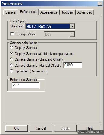
If you are testing a disc with Blu-ray or HD DVD, set the "Color Space - Standard" option to HDTV - REC 709.
If you are testing a disc with a standard DVD in NTSC format, set the "Color Space - Standard" option to SDTV - REC 601 (NTSC) .
If you are testing a disc with a standard DVD in PAL or SECAM format, set "Color Space - Standard" to PAL/SECAM.
Press "OK" to close the window.
Note: How you set this option does not actually affect the grayscale correction at all. This option is only useful for viewing the red/green/blue primary colors of your display as close as possible to the ideal values ​​set according to the SD or HD standard (we will discuss how to quantify the three primary colors and their meaning). In a machine that can play SD DVD and HD Blu-ray discs, setting your grayscale with Blu-ray Disc will work for SD DVD and Blu-ray discs. There is no reason to set different grayscales for SD and HD, because the reference target grayscale we want to achieve is the same for SD and HD. Different sources may be a little different on the signal, but they are slightly negligible. We found that it is not worth setting different gray levels for different sources. Set the grayscale with your best source (usually your DVD or Blu-ray/HD DVD player).
[page]Step 1.6: Remove the sensor from the box and plug it into the USB slot on your PC. Both the Eye-One and the Spyder2 have a cover that can be removed from the cymbal or diffuser.
This is the Spyder2 lid/slap:
This is the diffuser of Eye one:
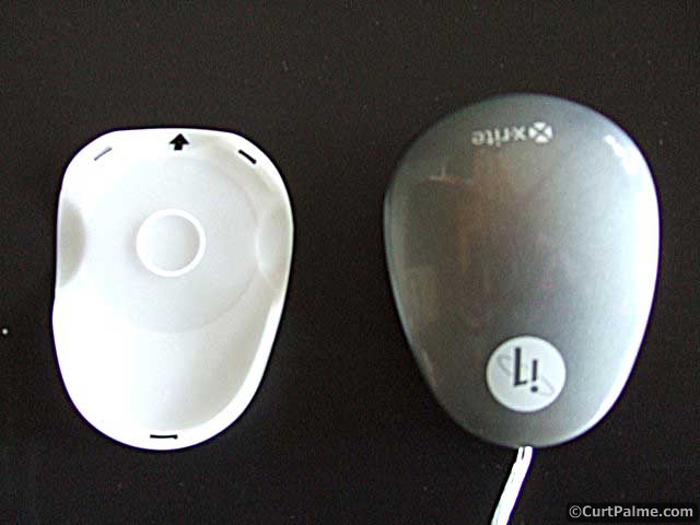
For Spyder2 users only: Keep this cover/filter on for all Display types including front Projector setups with a screen.
For Eye-One users only: Remove the diffuser for all types of displays. It is only suitable for measuring indoor light sources with the Eye-One software. We will never use it with our ColorHCFR software. The Eye-One Pro sensor has no diffuser.
Step 1.7: Open a new calibration file in ColorHCFR. This file stores all your "pre-corrected" data so that we can compare it to our "corrected" data. Select the menu "File-> New" to open a new calibration file in ColorHCFR and select "DVD Manual" to tell CoColorHCFR that you will provide the test pattern from the external test disc.
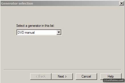
Press "Next".
Step 1.8: Select "Eye One" or "Spyder II" as the sensor from the list of available options.
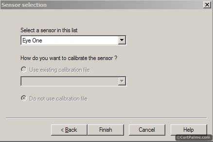
Press "Finish" and you will see a new window with a bunch of new messages appearing (only a few of us will actually use it):

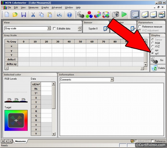
Step 1.9: We will display the data in xyY mode as it is the most commonly used way to match colors. In the "Display" window on the right, select the "xyY" option:
[page]
Although we are currently only interested in the measured light peak output ('Y' illuminance value), some explanations about xyY may be helpful. Please see the picture below:

This picture shows an internationally accepted method for all colors or the "color space" that the human eye sees. It is called the CIE 1931 color space. It is composed of "C ommission I nternationale de l ' E clairage" or "CIE" ( "International Commission on Illumination" in French) established in 1931, hence the name "CIE 1931", seems full of reasonable!
By changing the x and y values ​​we can correspond to any visible color in the human eye. The Y value is the brightness (or illuminance) of the color, and it is not shown in the figure. It must be represented by the axis of the third highlighted page (or screen, when you read it online). What we will do later is to change the "Y" value, from all black (0 IRE) to all white (100 IRE), read the value and try to adjust the color to make it fall in the middle of the white point, called D65. D65 stands for a point that has no color component at all: it is pure black, white or a variety of gray in the middle. The x,y coordinates of D65 are x=0.313, y=0.329. These magic numbers are what we use to measure the values ​​and try to achieve them.
Do you understand? If you are confused, don't worry! You don't need to know this to correct your grayscale, but knowing this basics will help you understand the operation of ColorHCFR software. As for now, however, we only need to measure the illuminance or the total light output, so now we only care about the part of Y reading.
Step 1.10 : We will now confirm that we have set the sensor in place. This will vary depending on the type of sensor. Select the menu "Measurements -> Sensor -> Configure". Users should set them to the following image according to the sensors they use (Eye-One or Spyder2).
For all types of displays, make sure the "Calibration Mode" is set to "LCD", except for the following:
The CRT Direct View (Picture Tube) display should select "CRT". Eye-One and Spyder2 must be set this way. The "LCD" should be selected for use with CRT rear projection displays and CRT projectors. Eye-One and Spyder2 must be set this way. If you sometimes have problems with software locks or taking too long (30-60 seconds) to read, you may want to try replacing them with "CRT" mode. Sorry, we are still trying to understand the logic behind these and the best mode for CRT rear projection displays/projectors. Users of plasma displays should select "Plasma" when using the Eye-One sensor. Spyder2 does not have the "Plasma" option, please use "LCD" instead. Use the Eye-One Pro sensor to select "Eye One Pro" as the display type. Even if your display is not using LCD technology, the "LCD" option is a suitable option for other digital displays such as SXRD, LCoS, DLP, etc. CRT, plasma technology, and Eye-One Pro sensors are the only exceptions that may be set to be other than "LCD."
Applicable only to Spyder2: The read time is the time the sensor is continuously turned on during measurement. Only Spyder2 requires this setting. (Eye-One does not need to set the read time to read correctly). A darker test pattern requires a longer read time or the reading will be incorrect. For test patterns above 20 IRE, the preset value of 300 ms is long enough. For 20 IRE and below, 1000 ms or even 2000 ms is sometimes necessary. Since we have to measure the bright test pattern first, we set the default value to 300ms.
For Eye-One only: You need to calibrate the sensor, otherwise ColorHCFR will pop up the window asking you to do this before you take your first reading. Set "Time during which device calibraion remains valid" to 0, so we don't need to redo the correction in the process. The next time you start ColorHCFR or unplug/replug Eye-One, you will need to recalibrate. Depending on the previously selected display type, the correction will be different:
LCD or plasma : Press "Calibrate internal sensor offsets" and place the sensor on a flat, dark, non-porous surface, preferably a black surface. The inside of the black DVD case is very easy to use. Make sure it is flat and there is no extra light coming in! Select "OK" to start the calibration.
CRT : The sensor needs to measure the update rate of your CRT. Display the test pattern for all white (preferably 100 IRE), from your test disc (see the steps below directly) and press "Calibrate internal sensor offsets". For the image tube display, simply place the sensor on the TV image tube. For CRT front/projection projectors, hold the sensor as close as possible to the screen or erect with your tripod as described below. The erection direction is not perfect, the sensor only needs to be able to measure the update rate. Select "OK" to start the calibration. Ignore the all-white window that appears on your PC/notebook - remember not to put your sensor on your PC/notebook display!
Press "OK".
Step 1. 11: We now need to adjust the direction of the sensor correctly.
If you're using a straight-type display (digital or CRT) with a rear-projection TV, it's very simple! Just as shown below (the load can be balanced on the cable), hang the sensor on the display That's it. Make sure it is stable and flat on the surface of the display. If you can't flatten it on the display surface, you can hold it by hand to keep it in the right position. If you are using a plasma display, be sure to let the sensor warm up for 30 minutes on the display, as it will affect the reading when the temperature changes. If you are using the Eye-One sensor, after 30 minutes of warming up, I would recommend redoing the sensor calibration.
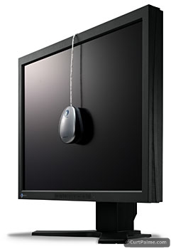
If you use a direct view display, this is all about placing the sensor, please skip the first part and go straight to the second part!
It takes a bit more work on the projection: we need to adjust the sensor to the perfect alignment, we can achieve this by adjusting the position of the sensor until the optical reading we get is the largest. Use some tape, rubber bands, or a free Spyder2 tripod mount (if you're using Spyder2) to attach the sensor to a tripod, don't need to be very secure, as long as you don't move when you measure it. We fixed it with some tape and it worked well.
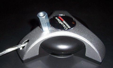
Forum member Andrew Low told us this secret: the standard 1/4〃-20 nut can be screwed into the standard three-legged head. Simply attach the nut to the Spyder2 as shown below:
Another option is to use the universal seat in our universal projector kit :

This versatile seat can be attached to any of the sensors mentioned in this manual without the use of tape or changing the way the sensor is used. For more detailed information or ordering please click here.
[page]
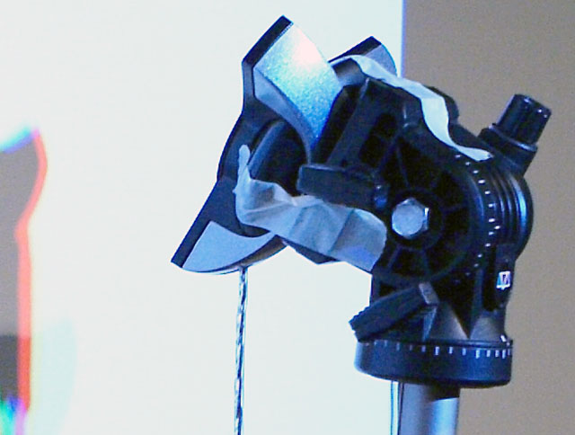
Use your tripod to position the sensor 3-4 inches away from the screen, slightly below the center, while tilting up against the curtain as shown:

Close-up picture:
The Eye-One sensor can be fixed in a similar way to a Spyder2 sensor, as long as it is attached to the tripod with tape or the like, so that the small suction cup under the sensor is facing the curtain.
If your projector is on the ground, you need to point the sensor aside and let it face the center of the curtain. There is currently no need for a perfect erection, and we will fine-tune it in subsequent steps.
Step 1.12: What we are going to do now is to play the brightest test pattern and fine tune the sensor position to maximize the Y reading, which confirms that our setup is perfect. Play your Digital Video Essentials: HD Basics test disc and jump directly to the option "Complete Program menu" -> "Advanced Video test patterns" -> 1080p or 720p -> "Window 100% w/ new PLUGE" 100 IRE window test pattern. 100 IRE means that the test pattern is 100% all white and 'window' means that the test pattern uses only a small portion of the picture (usually 10-18%). It looks like this:
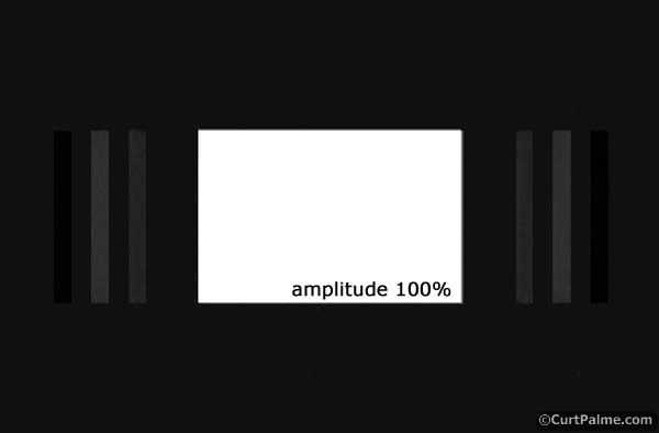
If you use a different test disc, your test pattern may or may not have a darker PLUGE gray strip pattern on both sides, so there is no problem.
Step 1.13: Start reading the reading continuously by the green triangle:

The sensor will begin to read the x, y, and Y readings and update them every few seconds. You should see the data update in the "Selected Color" window in the lower left corner:

We only need to care about the reading of Y (illuminance) now. The software fetches the Y reading and converts it to ftL. In this example, we can see that Y is 47.387 (13.8 ftL).
Step 1.14: Continue to look at the ftL reading and adjust the sensor in all 6 directions (near/far from the screen, left/right, up/down), slowly and systematically (only one change at a time) One direction) until the reading value is updated. For example, turn the sensor a few degrees in one direction, then wait until the reading of ftL is updated, continue to rotate while waiting for a new reading, and if the reading becomes smaller, turn in the opposite direction. Keep doing it until you get the maximum value, then adjust the pitch angle, then adjust the distance from the curtain and so on. Adjusting one direction at a time allows you to set up to the best position as soon as possible. This whole process will take you a few minutes. Keep adjusting until you get the maximum reading, which is where we want it. From now on, don't touch or move the sensor. If you move to the sensor, you must redo the program, otherwise your Y reading will not be the same.
The maximum light output reading also ensures that the sensor does not sense its own shadow (the darker portion than other white images). If the sensor senses its own shadow, the Y reading will be smaller.
By finding the maximum light output reading, we can determine that the erection is a full alignment projector and that we can get the most accurate reading. It also means that during our measurement, if we move to the sensor slightly, the x, y (color) readings we get from the sensor will not change, only the Y (illuminance) reading will change. Therefore, grayscale correction is not very demanding for erection.
Congratulations! You have now perfectly set up the sensor!
Advanced drives for fluid and gas handling applications with embedded energy monitoring, information management and process optimization.
Three Phase Inverter,Voltage To Frequency Converter,Frequency Note Converter,Industrial Automation Inverter
Wuxi Trenty Machinery & Equipment Co., Ltd. , https://www.elec-inverter.com