The main function of the microstepping stepper motor driver is to improve the accuracy of the stepper motor. However, with the development of technology, the microstepping stepper motor driver can also perform the stall detection calculation in real time and adjust the detection level according to different conditions. What's more, you can achieve silent drive. In the automotive power system, the microstepping stepper drive has become an indispensable part.
Two microstepping stepper drive performance PK
1. Microstep drive A4983 with converter
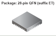
The A4983 is a DMOS microstepping driver with a converter that has the advantage of a low RDS(ON) output, self-driven current decay mode detection/selection, hybrid and slow current decay modes, low power dissipation synchronous rectification, internal UVLO, And cross current protection is possible. Compatible with logic power supply 3.3~5V, ultra-thin QFN package with thermal shutdown circuit.
Microstepping drive A4983 with converter
The A4983 is a complete microstep motor driver with built-in converter for easy operation. The product operates bipolar stepper motors in full, half, 1/4, 1/8 and 1/16 step modes with output drive performance up to 35 V and ±2 amps. The A4983 includes a fixed off-time current regulator that operates in slow or mixed-attenuation mode.
The converter is the key to the ease of implementation of the A4983. Simply input a pulse into the “step†input to drive the motor to generate a microstep. There are no phase sequence tables, high frequency control lines or complex interfaces in this program. The A4983 interface is ideal for applications where complex microprocessors are not available or overloaded.
The chopping control in the A4983 automatically selects the current decay mode (slow or mixed). When a signal appears at the “step†input pin, the A4983 determines if the step will produce a higher or lower current in each motor phase. If the charge produces a higher current, the decay mode is set to "slow" attenuation. If the charge produces a lower current, the current decay is set to “mixed†(starting with a period of 31.25% of the fixed turn-off time set to fast decay, then setting the cut-off residual period to slow decay.) This current-attenuation control scheme can Reduce audible motor noise, increase step accuracy and reduce power consumption.
2. Microstep drive A4988 with overcurrent protection
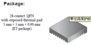
The A4988 is a DMOS microstep driver with converter and overcurrent protection. It has the advantages of low RDS (on) output, automatic current decay mode detection/selection, hybrid and slow current decay modes, low power dissipation synchronous rectification, internal UVLO, and cross current protection. Compatible with logic power supply 3.3~5V, with thermal shutdown circuit, ground short circuit protection, load short circuit protection. There are also five optional step modes: Full, 1/2, 1/4, 1/8 and 1/16.
Microstepping drive with overcurrent protection A4988
The A4988 is a complete microstep motor driver with built-in converter for easy operation. The product operates bipolar stepper motors in full, half, 1/4, 1/8 and 1/16 step modes with output drive performance up to 35 V and ±2A. The A4988 includes a fixed off-time current regulator that operates in slow or mixed-attenuation mode.
The converter is the key to the ease of implementation of the A4988. Simply input a pulse into the “step†input to drive the motor to generate a microstep. No phase sequence table, high frequency control line or complex interface programming is required. The A4988 interface is ideal for applications where complex microprocessors are not available or overloaded.
The chopping control in the A4988 automatically selects the current decay mode (slow or mixed) during microstep operation. In mixed-fade mode, the device is initially set to decay quickly during a portion of the fixed downtime and then slowly decay for the remainder of the downtime. Hybrid attenuation current control schemes reduce audible motor noise, increase step accuracy, and reduce power consumption.
An internal synchronous rectification control circuit is provided to improve power consumption during pulse width modulation (PWM) operation. Internal circuit protection includes: thermal shutdown with hysteresis, undervoltage lockout (UVLO) and cross current protection. No special power sequencing is required.
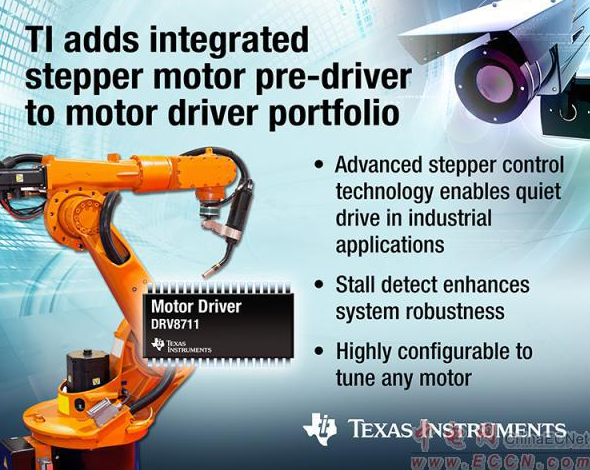
TI's integrated stepper motor pre-driver
The stepper motor driver DRV8711 supports the high configurability of best-in-class on-chip microstepping indexers, as well as stall detection and advanced current regulation for easy and efficient adjustment of any motor. The external MOSFET controls the stepper motor, supports minimum heat dissipation, and has a scalable output current that is 20% higher than competing products, allowing designers to customize their designs. This stepper motor front drive is also suitable for a variety of industrial applications, including textile machinery, video security monitoring, ATM machines, robotics, office automation equipment, and stage lighting.
DRV8711 physical map
The DRV8711's customizable driver stage: the gate driver supports up to 200mA of source current per 400mA of buck current and supports adjustable slew rate, dead time and on-time to meet application requirements. The device drives an external N-channel MOSFET that supports a built-in charge pump, providing more design options and a lower cost solution. Its smooth motion profile enables higher performance: the stepper motor is driven by an integrated microstepping indexer that supports up to 1/256 microstepping performance. In addition, the DRV8711 adaptive blanking time and various current decay modes (including slow, fast, mixed and auto-mixed attenuation) enable smooth motion curves to optimize motor performance. Designers can easily detect stalls with internal stall detection features, or detect optional stalls (BEMF) outputs to detect stalls and take corrective action with an external controller. This helps designers minimize motor stall disturbances;
In addition to the above features, the DRV8711 is also easy to use and highly configurable. The SPI interface allows the customer to program the output current, microstep mode, current decay mode, and stall detection functions, reducing system complexity and simplifying design compared to competing devices. The DRV8711 protects against motor overcurrent, pre-driver overcurrent, overtemperature, and undervoltage fault conditions to support system protection and achieve high system reliability and robustness.
Extended reading: Stepper motor microstep principle
A stepping motor is an open-loop control element stepping motor that converts an electrical pulse signal into an angular displacement or a linear displacement. In the case of non-overload, the speed and stop position of the motor depend only on the frequency of the pulse signal and the number of pulses, and are not affected by the load change. When the stepper driver receives a pulse signal, it drives the stepper motor. The set direction is rotated by a fixed angle called the "step angle" whose rotation is performed step by step at a fixed angle. The angular displacement can be controlled by controlling the number of pulses to achieve the purpose of accurate positioning. At the same time, the speed and acceleration of the motor rotation can be controlled by controlling the pulse frequency, thereby achieving the purpose of speed regulation.
Must-have Feature:
Glass-lid
Drainage Spouts
Locking Lid.
Non-Stick Coating.
Adjustable Steam Vent
Heat-Resistant Handles.
Electric Skillet
Shaoxing Haoda Electrical Appliance Co.,Ltd , https://www.zjhaoda.com