2 Theoretical study of micro-resistance test
This chapter mainly studies the related basic theories of high-precision micro-resistance testers.
Resistors can be divided into high resistance (100k or more), medium resistance (1 to l00k.) and micro resistance (1.) according to their size. This topic mainly studies the resistance measurement of micro ohm quantity resistance.
Resistance measurement usually uses a method of applying a current to measure voltage, and a method of measuring a micro-resistance is no exception. Considering that the microelectronic resistance is very small, in addition to accurately controlling the test current and accurately measuring the weak voltage on the resistance to be tested, it is also necessary to eliminate the influence of the wire resistance on the measured value and minimize the systematic error. The degree to achieve the purpose of measuring the resistance of the micro-resistance with high precision.
2.1 Basic principle of resistance measurement
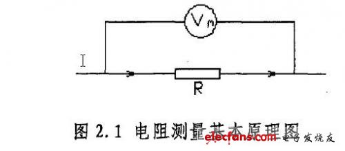
The tomb principle of resistance measurement is very simple, that is, using voltammetry (as shown in Figure 2.1), the voltage value U of the two sections of R is measured by a given current I through the resistor R, according to Ohm's law R=u/I Get the resistance value.
However, due to the influence of such factors as the wire resistance, the contact potential, the temperature difference potential, and the electrochemical potential in the detection circuit, when the resistance value is relatively large, these effects can be ignored. However, if the resistance value is extremely small, the absolute value of the error caused by these effects may even exceed several orders of magnitude of the resistance to be tested. It is necessary to study where these errors come from, how to reduce or even eliminate them, and it is possible to use higher precision. The resistance value of the micro resistance was measured.
2.2 Error analysis of DC micro-resistance measurement
When measuring resistance with voltammetry, a DC current source is used; and a small resistance value corresponds to a weak signal. Therefore, it is necessary to first study the noise in the weak DC signal detection in the general sense, and then to the error source in the DC micro-resistance measurement.
2.2.1 Noise theory for weak DC signal detection
Generally, interference noise can be defined from two angles. First, it is defined from the loop angle, the noise caused by the random fluctuation of voltage or current caused by the random motion of the charge carrier; secondly, from the perspective of signal analysis, pollution or Undesired signals that interfere with useful signals are called noise
There are many types of interference noise, and different detection methods should be adopted for different types of interference noise signals. Before performing signal detection, the nature of the signal should be analyzed in depth, and the object of detection should be clarified to determine the detection principle, method and instrument.
2.2.1.1 Detection of inherent noise sources inside the circuit
The noise generated inside the detection circuit component is called inherent noise, which is caused by the random motion of the charge carrier.
1. Thermal noise of the conductor's own thermal noise conductor
It means that any conductor, even if it is not connected to the power supply, does not have any current passing through the conductor, and it will also exhibit noise voltage fluctuations at both ends. Thermal noise is generated by random random thermal motion of the electrons inside the resistor. The magnitude of the thermal noise depends on the temperature. The higher the temperature, the more intense the thermal motion of the free electrons in the conductor, and the higher the noise voltage. Once the temperature is lowered, the heat is reduced. The noise will be reduced. The magnitude of the amplitude is also related to the resistance value of the conductor. For large resistors, the influence of the thermal noise of the conductor is correspondingly smaller, and for the micro-resistor, the influence is large. For systems that detect forest v-level or even nV-level weak signals, the adverse effects of thermal noise on the measurement accuracy of electrical resistance cannot be ignored.
2. Contact noise between conductors: Acoustic contact noise, also known as 1/f noise, is caused by random fluctuations in the conductance of the contact points of the two conductors. Any device with unfavorable conductor contact has contact noise; 1/f noise The amplitude distribution of the current is Gaussian, and its power spectral density function is now proportional to the reciprocal of the operating frequency f. This (f) can be expressed as:

Since Sf(f) is proportional to 1, the lower the frequency, the larger the power spectral density of this noise, and the amplitude of 1/f noise in the low frequency band may be large; an excessive amount of resistance inside the resistor due to fluctuations in resistance Noise is also a kind of 1/f noise; the rms value of excess noise voltage of several resistors is given below (measured in the range of 10 times per 1v voltage across the resistor):
Pure carbon resistance: 0.1 to 3.0 uv
Carbon film resistance: 0.05-0.3uv
Metal film resistance: 0.02 - 0.2uv
Therefore, in order to be able to effectively measure weak signals, the measurement bandwidth should be reduced as much as possible.
3. Burst noise
The cause of the popping noise is that impurities in the semiconductor (generally metal impurities) randomly emit or trap carriers in the PN junction. Burst noise usually consists of a series of random current pulses of different widths and amplitudes. The pulse width is generally on the order of a few microseconds to 0.15. The pulse amplitude is generally 0.01"A-0.001 forest A, and its probability of occurrence is less than several hundred. Hz, the burst noise depends on the manufacturing process of the conductor and the impurity condition in the conductor material. If the burst noise is amplified and sent to the horn, a sound similar to popcorn can be heard. Since the burst noise is current type noise, it should be as much as possible To reduce the resistance of the relevant resistors in the circuit, filter measures should be used.
Led rear view backup camera come with infrared or white LED , really help you checking blind spots in darkness, make you parking and reversing more convenient.
- [Car Backup Camera with LED]Really help you checking blind spots in darkness make you parking and reversing more convenient
- [Waterproof IP68 Rating]Work great in all weathers, you don't need to worry about parking a car in rainy day
- [Low power consumption design]Consume less than 50 mA, Don't worry about heat will affect the backup camera's service life,It can be used for a long time.Operating temperature in -4℉ to 176℉
- [32FT total length wires]We offer LONGER WIRES to ensure Rear View Camera can perfect fit for most types of vehicles
-
[Customer Service]30-Day Money Back Guarantee; 12 Month Replacement Warranty And Lifetime Support .

Backup Camera For Car,Led Rearview Backup Camera,Led Car Backup Camera,Led Hd Backup Camera
Shenzhen Sunveytech Co.,LTD , https://www.sunveytech.com