With the increasingly severe counter-terrorism situation at home and abroad and the frequent occurrence of various emergencies, higher requirements have been placed on whether the armed police forces can complete their tasks quickly and effectively in various complex and dangerous environments. Traditional reconnaissance methods have been unable to meet the needs of the situation, such as major natural disasters, which led to the inability of rescue work; the anti-terrorism or assisting arrests cannot effectively track the suspects. The emergence of unmanned reconnaissance aircraft has brought convenience to the personnel on duty, but the vibration generated by the drone itself during the reconnaissance process will make the image shooting appear jittery, thus greatly affecting the correct decision of the commander. The traditional autopilot uses an inertial measurement unit to obtain the aircraft's attitude information, including angular velocity (gyro) and accelerometer. The gyro is used to measure the attitude angle and angular velocity of the aircraft; the accelerometer is used to measure the two horizontal projections under general gravity acceleration, and the current attitude of the aircraft can be converted through the triangular relationship, that is, the pitch angle and roll angle. However, the attitude information measured by the accelerometer is very susceptible to interference from aircraft vibration and its own acceleration during maneuvering. The measurement accuracy error is generally large and the stability is poor, which affects the reconnaissance effect. In order to solve the flight stability of the UAV, a full-attitude stabilization control system composed of a three-axis gyro and an inclination sensor was studied to improve the stability of the UAV when performing tasks.
l System featuresThe gyro and the inclination sensor form a full attitude stabilization control loop. The angular velocity information measured by the gyro is used as a feedback control for stabilization, which makes the aircraft more "blunt" to operate, so that the roll angle and pitch angle of the aircraft can be measured by the tilt sensor. Then, the angular rate information measured by the gyro and the attitude angle measured by the tilt sensor are subjected to strapdown calculation to obtain the fused attitude information. This more complex strapdown algorithm can greatly improve the attitude accuracy.
2 Attitude stabilization control law hardware designUAV attitude stabilization control belongs to internal loop control, which includes attitude maintenance and control, speed control and other modes. Inner loop control is based on the three-axis gyro and the inclination sensor to obtain the flying attitude of the UAV, and through the control of the elevator and rudder, the flight attitude is stabilized and controlled. As the core loop of flight control, the inner loop control is also the basis of outer loop control such as flight altitude and track. The outer loop control is based on the GPS position, heading signal, and barometric altitude signal of the altitude sensor. It uses the navigation control method to calculate the aircraft's scheduled and actual routes.
As the basis of external loop control, UAV inner loop control plays a vital role in its ability to fly stably. In this system, the inner loop is an attitude stabilization control loop composed of a three-axis gyro and an inclination sensor. It is mainly composed of the main control microcontroller, A / D sampling chip, three-axis gyroscope and inclination sensor. The main control MCU is connected to the A / D sampling chip through the SPI serial bus. The A / D sampling chip is used to obtain the angular rate of the three-axis gyroscope and the roll angle and pitch angle of the inclination sensor. The pitch and roll attitude information of the aircraft. The main interface connection is shown in Figure 1.
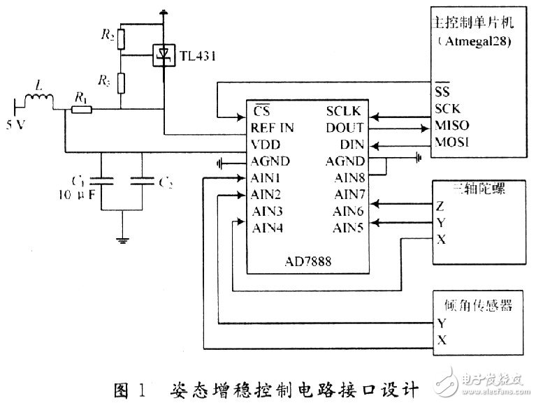
In Figure 1, AD7888 is a high-speed, low-power 12-bit analog-to-digital converter that can achieve a transmission rate of 125 KSPS and has 8 analog input channels.  It is a chip-select pin. This pin has two functions, namely starting the AD7888 converter and formulating the transfer of serial data, and the single-chip pin PB0 (
  ) Connected. SCLK is a serial clock input pin, which provides a serial clock signal through an external single-chip ATmegal28 pin PBl (SCK). DIN is the logic data input terminal, and DOUT is the logic data output terminal, which are connected to the pins PB2 (MOSI) and PB3 (MISO) of ATmegal28, respectively.
The external reference voltage range is Vref ~ VDD (Vref = 1.2 V). In order to obtain a stable reference voltage, a reference voltage circuit composed of TL431 is used. The TL431 produced by Texas Instruments (TI) is a three-terminal adjustable shunt reference source with good thermal stability. Its output voltage can be set to any value in the range from Vref = 2.5 V to Vref = 36 V with resistors R2 and R3.
The one-chip computer ATmegal28 and AD7888 are connected through a serial communication interface SPI, which are respectively configured as a master and a slave. The SPI bus allows high-speed synchronous data transmission between ATmegal28 and peripherals.
The three-axis gyro is mainly used to measure the angular velocity of the pitch angle, roll angle and yaw angle of the UAV during flight, and calculate the angle change based on the integral of the angular velocity. The EWTS82 (hereinafter referred to as S82) of Panasonic Corporation of Japan is used in this system, and its principle is to convert the earth's deflection force (Creoli force) generated by the oscillation of the tuning fork into an electrical signal during rotation. The three-axis gyro is composed of a sensor device, a tuning fork drive circuit, and a signal processing circuit. This gyro is an analog device, with a measuring range of +80 ~ -80 (°) / s, single power supply (+5 V DC) power supply, good suppression of zero drift and other advantages. In addition, its low price can greatly reduce development costs.
The tilt sensor uses the high-precision dual-axis tilt sensor SCAl00T produced by VTI Technologies of Finland. The sensor has a small size and light weight. It contains a silicon sensitive capacitive sensor and an ASIC special integrated circuit, which has both internal temperature measurement and compensation functions, and self-detection function. The maximum output range of a single axis is about -40 ~ +40 ℃, and the effective output range is- 30 ~ + 30 ℃. When the sampling frequency is 8 Hz and below, an output resolution of 0.002 ° can be obtained. The output frequency of the serial peripheral interface SPI is 500 kHz. The frequency response is controlled by the sensor element and can withstand mechanical vibrations greater than 20 000g. Its main features are: x, y dual-axis high-resolution bidirectional measurement, single power supply (+5 V DC) power supply, low operating current (3 mA), low noise, wide operating temperature range (-40 ~ +125 ℃ )Wait.
3 Attitude stabilization control software designThe input of the entire flight control system is the flight state value collected by the sensor, and the output is the control variable (rudder value and engine thrust) of the aircraft state equation, so the flight control system is essentially a multi-channel control system, that is, multiple Input / multiple output control system. Among them, the core control loop of the flight control system is a flight attitude stabilization and control loop based on the attitude angle (pitch angle / roll angle) feedback signal, that is, the inner loop.
On the basis of the inner loop, outer loops such as altitude maintenance and track control are introduced.
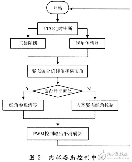
In the flight control system's attitude stabilization control loop, the three-axis gyroscope feeds back the aircraft's pitch, roll and yaw angular rates in real time. In addition, the pitch and roll rates of the three-axis gyro and the pitch and roll angles measured by the inclination sensor are respectively used for attitude strapdown calculation. The main control MCU uses the timer / counter O timing interrupt to perform the inner loop attitude control at intervals of 30 ms. The control flow is shown in Figure 2. Due to the symmetry of the aircraft along the longitudinal plane, UAV flight control can be divided into relatively independent longitudinal control and lateral control channels.
(1) Lateral and lateral control channel: The lateral and lateral motion of the drone, that is, the rolling and yaw motion of the drone, is mainly achieved through the aileron channel. There are roll angle feedback and roll angle rate feedback in the lateral control channel, these two constitute the core loop of the roll channel-the inner loop. In addition, the heading deviation feedback only needs to be picked up when the drone is in direct flight, course tracking, or autonomous navigation, to stabilize the flight direction of the drone; the lateral offset feedback is only when the drone enters autonomous navigation Access is required to control the drone to track the pre-set flight route; error integral feedback is only accessed when the drone is in direct flight to eliminate the influence of factors such as the left and right asymmetry of the drone and improve unmanned Accuracy of aircraft heading control and symmetry of left and right turns.
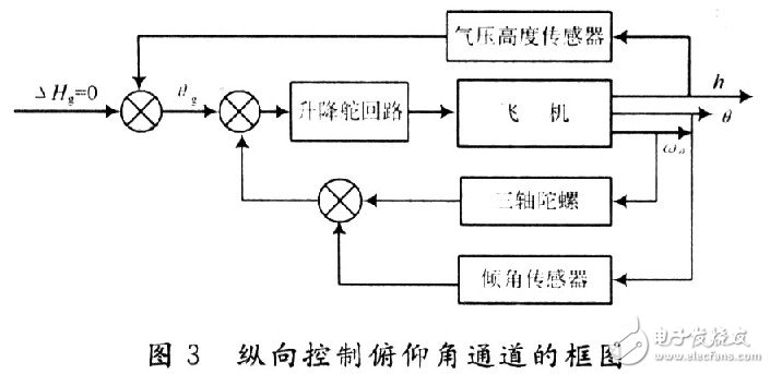
(2) Longitudinal control channel: The vertical motion of the drone refers to the pitch and lift movements of the drone. The longitudinal motion law of the drone is realized by manipulating the elevator of the drone. There are pitch angle feedback and pitch angle rate feedback in the longitudinal control channel, which constitute the core control loop of the longitudinal channel-the inner loop. In addition, there is height difference feedback. Only when the drone is flying at a fixed height, it needs to be connected to stabilize the flying height of the drone. The block diagram of the longitudinal control pitch angle channel is shown in Figure 3.
The flight process of a drone can usually be divided into several relatively independent flight segments. A most basic autonomous flight project can be divided into 6 flight segments: take-off phase, outbound level flight phase, turn phase, return flight level flight phase, hover phase and landing phase. The tasks of each flight segment are relatively independent, and the complex flight status of each flight segment is decomposed into several basic flight tasks: level flight, turning, lifting and so on. In this way, the basic flight tasks such as level flying, turning, and lifting of the UAV can be coordinated through relatively independent longitudinal control channels and lateral control channels.
4 ConclusionIn the UAV, the flight control system is the main component, and the attitude stabilization control is an effective method for the UAV to successfully perform various tasks. Based on practical application, this paper introduces in detail the hardware implementation and software design of a full-attitude stabilization control system based on a three-axis gyro and an inclination sensor, and applies it to a certain type of unmanned aerial vehicle. The flow and the law of inner loop attitude control were analyzed and studied in detail. After more than 100 test flights, the attitude stabilization control system based on the three-axis gyro and the inclination sensor not only meets the task requirements at this stage, but also achieves good results. It provides a set of practices for the development and development of similar drones Effective method.
PLC, that is, planar optical waveguide, that is to say, the optical waveguide is located in a plane.
As everyone is familiar with single-layer circuit boards, all circuits are located in a plane of the substrate. Therefore, PLC is a kind of technology, it does not refer to a certain type of product, let alone a splitter! Our most common PLC splitter is made of silicon dioxide (SiO2). In fact, PLC technology involves a wide range of materials, such as glass/silicon dioxide (Quartz/Silica/SiO2), lithium niobate (LiNbO3), III-V semiconductor compounds (such as InP, GaAs, etc.), silicon-on-insulator (SOI/SIMOX), silicon oxynitride (SiON), polymer, etc.
Devices based on planar optical waveguide technology solutions include: Splitter, Star coupler, Variable Optical Attenuator (VOA), Optical switch, Optical comb ( Interleaver) and Array Waveguide Grating (AWG), etc. According to the requirements of different applications (such as response time, ambient temperature, etc.), these devices can be made by choosing different material systems and processing techniques. It is worth mentioning that these devices are all optical passive devices and are independent. They can be combined with each other or with other active devices to form high-end devices with different functions.
Optical Fiber, ABS BOX PLC splitter,Fiber Cable Splitter
Shenzhen GL-COM Technology CO.,LTD. , https://www.szglcom.com