In the air of a region, what types of TV signals are present and what is their field strength? This is a critical concern for radio and television regulatory authorities as well as non-committee organizations. This article will explore this topic from an electronic measurement perspective.
First, TV signals and their field strength
As is widely known, a television signal operates within the frequency range of 42–860 MHz, carrying both video and audio information. Analyzing these signals involves video and audio analysis. However, when it comes to signal strength, the focus is on the level of the line synchronization signal. Since this signal is pulsed, its peak value is used as the measurement standard.
Field strength measurement and field strength meters have been covered in another article on the Hauge website, titled "Field Strength Measurement and Field Strength Meter." Here are two key points to note:
- Field strength refers to the magnitude of an electrical signal induced by a unit length antenna at a point in the air, measured in microvolts per meter (μV/m). It should not be confused with voltage units like V, μV, or dBμV, or power units such as dBm.
- A field strength meter typically consists of a level meter (or spectrum analyzer) combined with a test antenna. In China’s cable TV industry, the term “TV signal level meter†is commonly used, and it measures the peak value of the signal.
Second, the measurement of television signals
The principle of measuring the field strength of TV signals in the air has been described in detail in the author's previous work on field strength measurement. The measurement setup is illustrated in Figure 1. Given the characteristics of TV signals, the level meter used should be a TV signal level meter, also known as a TV field strength meter, and the antenna must be suitable for the TV frequency range.
The field strength value E can be calculated using the following formula (1):
E = Er + K + Lf (dBμV/m) —--(1)
Where:
- E is the field strength value (dBμV/m)
- Er is the level value at the meter input port (dBμV)
- K is the antenna coefficient (dB)
- LF is the loss of the connecting cable (dB)
For a TV signal level meter, it's beneficial if it has a spectrum analyzer function. This allows for panoramic scanning across the desired frequency range, and you can use the cursor to lock onto specific signals. Beyond TV signals, there are many other signals in the air, such as communication, radio, and other wireless signals. Our goal is to detect TV signals. Therefore, the instrument should also support TV image display. Once locked, you can view the image and simultaneously measure the field strength, which helps monitor which TV stations are active in your area and identify any unauthorized ones.
Regarding the antenna, its frequency range should cover 46–860 MHz, and it should provide the antenna coefficient K. Different manufacturers may specify positive or negative values for K, so it's important to check the specifications when using them. For example, Anli uses a K value, while the domestic 900E uses a +K value.
If the connecting cable is 1–2 meters long, the loss can be ignored, meaning that the field strength is simply the meter reading plus the antenna coefficient:
E = Er + K —— (2)
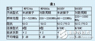
Figures 2 and 3 show antennas produced by Anritsu Corporation of Japan. The antenna coefficients K are shown in Figures 4 and 5 respectively. MP534A is a half-wave dipole type, and MP666A is a logarithmic periodic type. Their technical specifications are listed in Table 1.
Figure 6 shows a domestic 900E antenna. 900EV is a half-wave dipole type covering 40–220 MHz, and 900EU is a logarithmic periodic type covering 220–1000 MHz. The antenna coefficient is shown in Figure 7, and the technical specifications are given in Table 1.

Let’s take an example: The 900E antenna is connected to the PRK3C+ color TV image spectrum field strength meter. After turning on the PRK3C+, it operates in spectrum analysis mode, displaying multiple signals. We can move the cursor to locate the signal at 320.25 MHz and switch the instrument to TV receiving mode. When the image is captured, we can read the level value.
Set the level value to 68 dBμV.
Referencing Figure 7, the horizontal axis corresponds to 320.25 MHz, and the vertical axis shows a K value of 9 dB.
Therefore, the field strength is calculated as:
E = 68 dBμV + 9 dB = 77 dBμV/m
Third, several issues in field strength measurement
1. Measurement accuracy of field strength: To measure the field strength in the air, the antenna induces an electrical signal at a certain point. First, the antenna is directional, so it needs to be rotated to find the maximum signal. In terms of measurement accuracy, the main sources of error come from the instrument and the antenna itself.
New Arrival Linear LED Driver(Slim Driver)
Fahold has been specializing in LED Driver for 10 years. This new arrival linear led driver version, is combination of new market needs and fahold's powerful techniology.
This new version led linear drivers, has completely new function compare to fahold old one, it is much cost-effective, and adding Dali dimming; output current changeable by dip switch.
Dimming Linear Driver,Switching Power Supply, Linear LED Driver
ShenZhen Fahold Electronic Limited , https://www.leddriversupply.com