Based on the comparison of common gas sensing components, OPTOSENSE's latest infrared absorption methane gas sensor MIPEX was selected, and the wireless gas sensor node hardware circuit was designed. Based on the ZigBee protocol stack, the node software program is designed. The node is in a working/dormant alternating state with a period of about 10 min. In the case of three ordinary battery-powered situations, it is theoretically estimated that its working time can be more than 10 years, which is far from the traditional low-power gas sensing element. Far from being reached.
Gas accidents have always been a major threat to the safe production of coal mines. Although gas monitoring technology has continued to develop in recent years, gas explosions have occurred frequently. The existing coal mine safety monitoring systems at home and abroad are wired connections, which have great limitations. Since the sensor uses a wired connection, this is mainly limited to applications in the main mine. At the coal mining face with high gas concentration, due to the continuous mining of coal mines, various large-scale equipment on the working surface need to be continuously promoted, and the mutual position between the equipments is constantly changing. The wired monitoring network cannot follow the mines in time. Changes that result in monitoring blind spots. The application of wireless sensor networks in gas safety monitoring systems, combined with existing wired monitoring networks, to build a more comprehensive downhole gas monitoring system will help to improve the current problems in the field of gas monitoring.
In such systems, the sensor network nodes are battery powered and have very limited energy. However, the power consumption of commonly used low-power gas sensing components is as high as several hundred mW. How to reduce node energy consumption is a key problem to be solved by wireless gas monitoring networks.
1 hardware circuit design
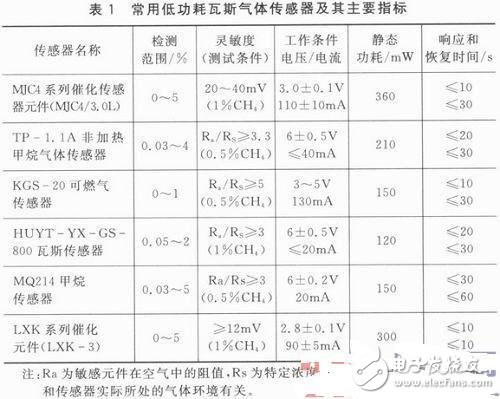
Table 1 lists the commonly used low-power gas sensing components and their main indicators. As can be seen from the table, the power consumption of commonly used low-power gas sensors is above 100mW, which is very disadvantageous for battery-powered wireless sensor nodes. Moreover, the sensing elements listed in the table have a certain response time, that is, after the sensing element is powered, it needs to wait for a response time to correctly reflect the gas concentration information. Longer response times limit the amount of time that a wireless gas sensor node can't work each time it collects data. For example, the response time of the TP-1.1A non-heated methane gas sensor is close to 20 s. If the gas sensor node uses the sensing element, when it collects data once, it is meaningless to collect data from the first 20 s from the power supply to the sensor. Because the sensing element is in the response phase at this time, its voltage value cannot accurately reflect the actual gas concentration information. Therefore, each time data is collected, the sensing element is powered for at least 20 s. For such high-power sensing elements, the energy consumed to acquire the data once is very large. This makes the designed wireless gas sensor node work time is too short, so that it can not meet practical requirements.
In the design of wireless sensor nodes, there is also a problem that the operating voltage of the sensing element is inconsistent with the operating voltage of the microprocessor and the wireless transceiver circuit in the node circuit. If the supply voltages of different modules in the node are different, the circuit needs to perform voltage conversion. The conversion of different voltages will increase the complexity of the circuit design, resulting in increased node energy consumption.
The infrared absorption methane gas sensor MIPEX produced by Russian OPTOSENSE company is designed by the principle of non-dispersive infrared technology (NDIR), and its light source adopts non-traditional energy-saving LED light source. The light source system uses an advanced algorithm to generate an optimized radiation spectrum, and the light is passed through a methane-filled optical system to a photodiode containing lead selenide and cadmium selenide to monitor the methane concentration. The sensor has a built-in temperature sensor and an integrated signal processing and temperature compensation system that outputs digital signals on its own. Digital signals can effectively avoid the effects of the external environment on their output signals. The digital signal output by the sensor follows the UART format.
The wireless transceiver chip selected in this paper is CC2430, and the power supply is powered by battery pack. As the battery energy is consumed, the voltage output of the battery pack changes greatly, and it is easy to exceed the operating voltage range required by the sensing component. Therefore, it is necessary to select a suitable voltage regulator device to provide a stable operating voltage for the sensor component and the wireless transceiver circuit. . The main considerations are as follows: 1 node is intended to be powered by 3 to 4 AA batteries, ie for voltage regulators, the input voltage range is 4.5 to 6 V; 2MIPEX sensor operating voltage range is 3 to 4.5 V, while CC2430 wireless transceiver The operating voltage range of the chip is 2 ~ 3.6 V, here the voltage is uniformly selected as 3.3 V, which requires the regulator output voltage to be 3.3 V; 3 wireless transceiver module maximum operating current is 27mA, MIPEX sensor average operating current It is 1 mA, so the selected regulator device is required to provide an output current of not less than 28 mA; the selected regulator device must be as small as possible to save energy when it is static.
Considering that the above four requirements are met at the same time, this paper selects the low-dropout linear regulator MH5333 produced by Shenzhen Minghe Technology Co., Ltd. Its input voltage is up to 10V, the output voltage is 3.3V, the maximum output current is 500mA, and the quiescent current is 1μA. It can be seen that the MH5333 voltage regulator device can better meet the above requirements.
The 3-5th battery is connected in series as the input of the regulator MH5333, and its output (3.3 V) supplies power to the wireless transceiver circuit and sensor components. The wireless transceiver circuit and the sensor component transmit data through the serial port. A pin LED is connected to pins P0.0 and P0.1 of CC2430 to facilitate the debugging of the program and the execution of the program. In order to reduce energy consumption, a pin of the CC2430 is used to control the power of the MIPEX sensor. The power supply requirements of the MIPEX sensor are that the power supply voltage is in the range of 3 to 4.5 V, and the output power is in the range of 0.02 to 0.25 W. The P1.0 and P1.1 pins of the CC2430 can provide a driving current of 20 mA, which can be seen from the CC2430. The output power of the P1.0 and P1.1 pins can meet this requirement. Here, the P1.0 pin of the CC2430 is selected to control the power of the MIPEX sensor. The TXD and RXD pins of the methane sensor MIPEX are connected to the P0.2 and P0.3 pins of the CC2430, respectively, to the RXD and TXD terminals of the asynchronous serial interface 0 of the CC2430.
2-node software design
The digital signal output by the infrared methane gas sensor MIPEX follows the UART format and requires a baud rate of 9 600, 8 data bits, 1 stop bit, and no parity. The MIPEX sensor's control commands follow the ASCII code, and each control command ends with a carriage return. Each MIPEX sensor has its own address, which ranges from 00 to FF. The factory default address is 00, and the user can rewrite it by himself. Since each wireless gas sensor node has only one MIPEX sensor, there is no need to modify its address.
The data query command of the MIPEX sensor is DATA. When the CC2430 needs to query the density information in the MIPEX sensor, it first sends a set of commands to the MIPEX sensor: 44 41 54 41 0D. The first 4 bytes are respectively corresponding to “DATAâ€. The ASCII value, the last "0D" is the ASCII code of the carriage return. After receiving the query command, the MIPEX sensor returns a value of Concl. The return value is a 5-digit ASCII code indicating the concentration information, and the end is still a carriage return (0Dh). For example, the methane gas concentration is 1.86%, and the sensor's return value is 00186.48 48 49 56 54 is 0 0 1 8 6 ASCII code, as shown below.

After the sensor is powered up, it takes 60 s of warm-up time. During this period, the sensor output is not the concentration information, generally after FFFF.60 s, the sensor will output the correct measurement value. Therefore, when designing the program for reading and writing the sensor, after the sensor is powered on for 1 min, the data query and read command are sent to it, otherwise the read data has no meaning.
The wireless transceiver chip CC2430 has four working modes: PM0, PM1, PM2 and PM3. Among them, PM3 mode is the most power-saving, but can only be awakened by external interrupts; PM2 mode is more power-saving and can be wake-up periodically. The low power setting here is for the CC2430 to operate in PM2 mode. The low-power implementation of the ZigBee protocol stack is divided into two parts: one is to automatically enter the low-power mode when no tasks need to be executed; the other is the low-power design when the CC2430 periodically collects gas concentration information. When the ZigBee protocol stack performs task polling, it automatically enters the low power mode if there is no task to be performed. The specific implementation is to call the osal_pwrmgr_powerconserve() low-power function in the protocol stack main loop program osal_start_system. This function takes the time of the next arrival time of the OS layer TImer as a parameter, and calls hal_sleep() to enter the PM2 sleep mode. If there is currently no task, then it will enter PM3. In the subsequent program, a sensor read event is set each time, that is, if it enters sleep mode automatically, it must enter PM2 mode. Set TImer2 (sleep timer) before sleep, wake up time is just equal to the arrival time of the next task, and then go to sleep again after completing the task.
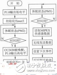
According to the operation requirements of the sensor, the wireless gas sensor is set to work according to the following procedure. The node is in the active/sleep alternate state, and one duty cycle is about 10 min. In the first 8 minutes and 30 seconds, the P1.0 pin of the CC2430 outputs a low level, and the control MIPEX sensor does not work. Then, the CC2430 enters a low-power mode of operation. After 8 minutes and 30 seconds, CC2430 is woken up, and the P1.0 pin outputs a high level, which supplies power to the MIPEX sensor. At this point, the CC2430 enters the PM1 low power mode. Since the warm-up time of the MIPEX sensor is 1 min, after setting 70s here, the CC2430 is woken up, starts to read the gas concentration information in the MIPEX, and then wirelessly transmits it. After the transmission is completed, set the next gas concentration read event for a period of 20 s. Within 20 s, the CC2430 automatically enters the low power mode. After 20 s, the event is triggered and sent to the application layer for processing, starting the above loop process. The specific process of programming is shown in Figure 1.
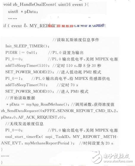
The workflow of the wireless gas sensor node is mainly implemented in zb_HandieOsalEvent(events), and the specific program is:
3-node energy estimation
In the designed circuit, the energy-consuming part is the voltage regulator circuit, CC2430 chip and MIPEX sensor. The CC2430 chip is in the PM2 low-power state for at least 8 minutes and 30 seconds in a working/sleep cycle (10 min). This article sets the PM2 low-power state, during which the current is 0.9μA. There is 70 s. The time is in the PM1 low power state, and the remaining 20 s is in the PM0 state. When the MIPEX sensor is working normally, its current is 1 mA. The energy of the general battery is expressed by the method of mAh. In order to estimate the working life of the designed node circuit, the mAh method is also used to represent the energy. Based on the above analysis, the energy consumed by the node circuit during a working/sleep cycle can be calculated. The energy consumption of the CC2430 in one cycle is approximately: Q1 = 0.9μA & TImes; 510 s + 0.2 mA & TImes; 70 s + 25 mA × 20 s = 514.459 mAs The energy consumption of the MIPEX sensor in one cycle is approximately: Q2 = 1 mA × 90 s=90 mAs The circuit designed in this paper is powered by three 1.5 V batteries, that is, the input is 4.5 V, and the output is 3.3 V. The efficiency of the MH5333 regulator is related to the dropout voltage. The efficiency of the linear regulator device (LDO) is generally 85% to 90%, and as the differential pressure decreases, its efficiency will increase. Assuming that the conversion efficiency is 85%, the energy consumption of the entire node circuit in one cycle (10 min) can be expressed as:
![]()
The energy of a common No. 5 battery is 600~700mAh, which can be used to estimate the working time of the designed node circuit under the condition of 3 battery power supply:

It can be seen that the wireless gas sensor node designed in this paper has a very low energy consumption. In the case of three ordinary 5th battery power supply, the working time can reach 3,797 days or 10 years. The setting of the sleep/sleep cycle can be shortened appropriately to improve the real-time performance of the monitoring. If the setup period is 5 min, then the working time is also about 5 years.
Conventional low-power gas sensing components consume more than 100 mW and have a response time of at least 10 s, so only the sensing components themselves consume a lot of energy. If the energy consumption of the signal amplifying circuit and the wireless transceiver circuit is added, the working/sleeping period is still 10 min, then the normal 3-cell 1.5 V battery meter can last for about one month. Therefore, the MIPEX sensing element has a superior performance in terms of low power consumption compared to conventional gas sensing elements. This also provides an effective way for the practical use of low-power wireless gas sensor nodes.
Conclusion
In this paper, the wireless gas sensor nodes designed by the low-power infrared gas sensors MIPEX and CC2430 can maintain long enough working time, which is far from being achieved by using traditional low-power gas sensing components. This is for propelling wireless gas sensor nodes. Further practicality is of great significance. However, the real-time response of the sensor nodes to the gas concentration response needs to be further improved. When the gas concentration exceeds the limit, it can send an interrupt trigger signal to the CC2430 to wake it up from sleep. However, you need to add hardware circuitry to achieve this. The sensor node can also be based on the level of gas concentration and the rate of change. To determine its work/sleep cycle. If the gas concentration is low and the rate of change is not large, a longer working/sleeping period can be set; if the gas concentration changes greatly, a shorter working/sleeping period is set; if the gas concentration exceeds the limit, it should be in real time. status.
Wall Bolier Manometer,Boiler Manometer Pressure,Pressure Gauge Pressure,Capillary Pressure Gauge Pressure
ZHOUSHAN JIAERLING METER CO.,LTD , https://www.zsjrlmeter.com