In the radar test system, it is often necessary to simulate the Japanese standard echo; at the same time, in order to test the anti-interference characteristics of the radar, it is also necessary to generate a signal for deceptive interference. DRFM (Digital Radio Frequency Memory) Because it can store and copy sampled signals with high fidelity, the test system can not only generate multiple false targets, but also generate distance towing interference and speed towing interference.
1 system composition and principleThe radar's test system needs to simulate the target's track. For high-speed sports targets, the control system needs to calculate control parameters in real time for use by function blocks. Because the DSP (Digital Signal Processor) chip adopts the parallel architecture of Harvard architecture, it has independent data storage space and program storage space, and its data and programs are stored in different memories. Using TI's DSP processing chip, TMS320C2000 series is a control-oriented processing chip, also has strong computing power, to adapt to the requirements of fast digital signal processing operations, more suitable for the use of this system, real-time calculation of download control parameters for Function block use.
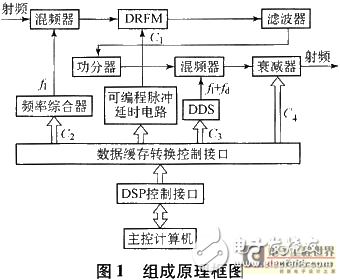
The test system consists of the following parts:
a) The system receives the radar signal through the antenna, and after mixing to the intermediate frequency, the intermediate frequency radar pulse signal is collected by the DRFM, and the collected data is stored in the memory for reading.
b) According to the command and interference parameters provided by the host computer, the DSP calculates the corresponding target delay and Doppler shift in real time for each update time, and stores the data in the corresponding latch.
c) The programmable pulse delay circuit delays the radar video pulse according to the parameters provided by the DSP, generates a data release signal of the DRFM, controls the D/A converter of the DRFM, generates an intermediate frequency pulse signal, thereby realizing the distance drag Lead interference.
d) The DDS (Direct Digital Synthesizer) module generates a corresponding Doppler shift signal according to the parameters provided by the DSP, and after the processing by the mixing circuit, realizes speed dragging or target speed simulation.
e) According to the motion trajectory of the false target, the DSP calculates the power attenuation caused by the distance of the false target in real time, controls the output electrical attenuator, and realizes the distance spoofing of the false target.
The block diagram of the target simulation and deception jamming system is shown in Figure 1.
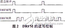
The data update of the DRFM read delay does not need to be updated for each radar pulse. This is determined by the speed of the target's motion. Generally, a 2 ms update is sufficient.
The delay time of the programmable delay circuit is controlled by the DSP, and the received radar video pulse is used as a starting point to calculate the delay parameter, and the number of the delay pulse is also controllable, so that multiple false targets or multiple generations can be controlled. Deceive interference signals.
Because DRFM can repeatedly copy stored signals, multiple analog targets or deceptive interference can be implemented all the way. For design flexibility, FPGA can be used to design a settable delay time and pulse with enable end. A number of pulse delay circuits can be designed in the FPGA as needed to design multiple single-pulse delay circuits, and then add these pulses to obtain a pulse with independent delay setting to simulate the target trajectory of independent motion. In this way, target simulation and deception jamming, multi-target simulation or multiple deception jamming signals can be achieved simultaneously with only one channel. The control timing for DRFM is shown in Figure 2.
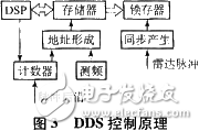
When only one target of a channel needs to be simulated, only the calculated Doppler shift parameters need to be sent to the latch. However, it is often necessary to simulate multiple targets or to simulate a target and its corresponding deception jamming. At this time, it may be too late to take control of each parameter to the latch. After the DSP calculates the distance and Doppler shift of multiple targets to be simulated, the Doppler frequency shift parameters are stored in the RAM in the order of the analog target relative to the radar signal distance, since the DDS is set to It takes time to stabilize the work, the first control parameter is sent by the radar sync pulse, and the other parameters are updated at the trailing edge of each pulse. For frequency agile radar, Doppler shift is frequency dependent. For example, when measuring to radar frequency recalculation, when the simulated target is close to the test system, the real-time update time is too late, because the target motion is not fast. The parameter update time is taken by pre-calculating the Doppler frequency shift and downloaded into the memory, and the frequency is used as the address when the memory is read. When the frequency is changed, the Doppler shift of the frequency at the moment can be obtained in real time. The circuit principle is shown in Figure 3. The control circuit is similar to the power variation when simulating the distance, because the circuit is simpler than the frequency, and the circuit is simpler than the control of the Doppler shift, and will not be described in detail.
A single channel to achieve multiple simulation targets or deception interference will reduce the amount of equipment and reduce the cost of the system, but when the two targets are close, the speed is different, and the number of simulation targets is large, one channel will be difficult to achieve. This can be done by adding channels. Since it communicates with the host computer through the serial port, this poses a problem, that is, how to easily synchronize the signals between the two channels.
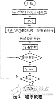
The following two channels (one channel used as a simulation target and the other channel used as a corresponding deception jam) are used as an example to introduce the implementation of channel synchronization. The motion parameters of the simulated target are downloaded to the main analog channel, and the channel for deceptive interference is downloaded. The computer needs to download the target parameter and the interference parameter together. When the DSP calculates, the received radar video pulse is used as a reference value to calculate the interference update time. Distance and speed. Since the timing of such a starting point is unknown, each DSP is updated independently, it will be difficult to guarantee the consistency of the deception jamming and the simulation target time. The main channel DSP can be taken as the main channel, and the interrupt signal is sent when the data is updated, and the other receives the update interrupt. To update the data, in order to ensure the simultaneity of each data update, two latches are taken, and the received radar video pulse generates a sync pulse to latch the data. The program flow is shown in Figure 4.
This paper introduces the real-time control method of Doppler frequency shift parameter in single channel multi-target simulation, and the real-time control method when multiple channels simulate multiple signals, and proposes a solution to signal synchronization. Although multi-target simulation is used for single-channel simulation, the targets with different simulation distances and different speeds have limitations, but the control circuit is simple and effective, stable in operation, low in equipment cost, and has practical value. It has been widely used in radar target simulation and interference generation equipment.
Shenzhen Kaixuanye Technology Co., Ltd. , https://www.iconlinekxys.com