**Basic Principle of High-Frequency Transformer Shielding**
Many engineers are familiar with the practice of shielding switching power transformers by inserting a winding between the primary and secondary windings, especially when grounded. However, not everyone fully understands the underlying mechanism behind this technique. Let’s take a closer look at how this works and why it's effective in reducing electromagnetic interference (EMI).
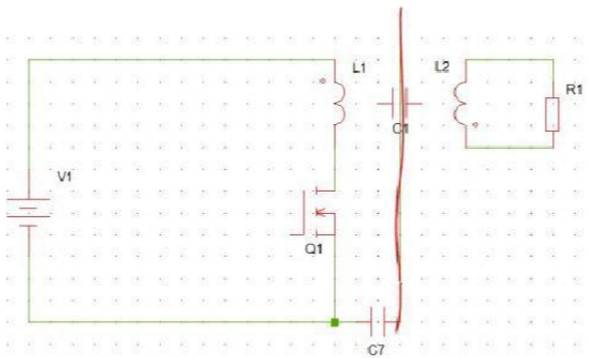
The main EMI propagation path typically involves stray capacitances between components and ground. For example, the parasitic capacitance between the MOSFET or diode and the heat sink, as well as the capacitance between the heat sink and ground, can couple noise into the LISN (Line Impedance Stabilization Network), which is then measured through a sampling resistor.
In the absence of shielding, one common approach is to use a Y capacitor (e.g., 472) connected between the ground of the sampling resistor and the ground of the output capacitor. This helps to provide a low-impedance path for noise currents, reducing their impact on the system.
So, what happens when we add shielding? As shown in the diagram below, the shield divides the original capacitance into two parts—primary and secondary. Each side is grounded separately, creating a more controlled path for noise to be redirected away from sensitive areas.
By introducing a metal plate between the primary and secondary windings, the parasitic capacitance between them can be significantly reduced. This allows the noise current to bypass the main circuit and flow directly to ground through the shield.
Another way to achieve this is by using a copper or aluminum foil wrapped around the transformer, ensuring that the ends are not shorted and properly insulated. This method provides a physical barrier that minimizes capacitive coupling between windings.
There are different methods for adding shielding to high-frequency transformers:
1. **Copper or Aluminum Foil Shield**: Wrap a long strip of conductive material between the primary and secondary windings, making sure not to short the ends. The shield should be insulated on both sides and grounded via welding or wrapping.
2. **Wound Wire Shield**: Use a thin enameled wire (diameter 0.1–0.3 mm) to wrap around both the primary and secondary windings. One end is grounded, and the other is left open. This method also requires insulation on both sides.
When using copper foil, it’s important to ensure that overlapping sections are insulated. Otherwise, the overlapping area may form a shorted loop, which can actually worsen EMI issues.
In terms of performance, both wire and copper foil shielding offer similar levels of effectiveness. However, each has its own advantages depending on the application. Wire shielding is often more cost-effective and easier to automate, making it ideal for mass production. It also offers greater flexibility in design, such as adjusting the starting point, ending point, and winding direction of the shield.
Additionally, some copper wire shields are used as supplementary windings to fine-tune internal capacitance, allowing for better control over the transformer’s electrical characteristics. This makes them particularly useful in high-frequency switching transformers where precise tuning is essential.
In summary, proper shielding in high-frequency transformers plays a crucial role in minimizing EMI and improving overall system performance. Whether you choose copper foil or wire-based shielding, understanding the principles behind it will help you make informed decisions in your design process.
Valve Regulated Lead Acid Battery
Valve Regulated Lead Acid Battery,Lead Acid Battery,Vrla Battery,12V 200Ah Lead Acid Battery
Henan Xintaihang Power Source Co.,Ltd , https://www.taihangbattery.com