The JEDEC standard (JESD216) Serial Flash Discoverable Parameter (SFDP) [1] is a parameter table for describing the serial flash function that can be queried in serial Flash. The article mainly introduces the structure, function and function of this serial Flash function parameter table, and gives its specific application in system design.
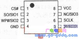
1 Introduction to Serial Flash Serial Flash is a SPI interface NOR Flash, which is a non-volatile storage device and is mainly used to store the system startup program. It is characterized by small size, few pins, simple interface and easy expansion. The main package is 8 pins, with chip select, data input, write protection, ground, data output, clock, pause and voltage pins, as shown in Figure 1. A serial data transmission method that is commonly used in one input and one output eliminates a large number of data lines, address lines, and control lines of parallel flash. Some serial flash can support four-in and four-out data transmission modes by greatly reducing the number of package pins, and can greatly improve the data output rate. At present, the maximum frequency can support above 104MHz, and the overall data transmission rate has exceeded the data transmission rate of general parallel Flash. Supported by the main chip function and port, serial Flash can replace parallel Flash in some system applications, which not only reduces the system printed circuit board volume, but also reduces system wiring and enhances the overall electromagnetic compatibility of the system. From the perspective of the overall system solution, compared to the main chip supporting parallel Flash, the main chip supporting only serial flash can greatly reduce the number of pins in the storage port, which is not only conducive to the reduction of the main chip area. It is also very beneficial for the overall plan offer. Therefore, serial Flash has been accepted and favored by more and more developers and designers, and is widely used in many fields such as computers, consumer electronics, wireless communications, automotive and industrial control.
2 JESD216 Background of SFDP Standards With the continuous expansion of the serial flash market, the instructions, functions and features of serial flash are also increasing, and the functions and features of various manufacturers on serial flash devices cannot be completely consistent. For example, in the sector erasing function, the 4kB, 32kB, and 64kB erasing operations have corresponding instructions, but there are some differences in instructions and functions between devices of different manufacturers. In order to accurately complete the compatibility test of the system or to consider the capacity upgrade, the development and design personnel need to read the product specifications of each serial flash in detail to understand whether the distribution and definition of the pins are consistent, and the operation needs to be used. Whether the function instructions are fully compatible, so that the underlying device driver software is supplemented and modified accordingly, or even changed to hardware, which undoubtedly brings some inconvenience to the design, maintenance and update of the project. Therefore, serial Flash devices urgently need a unified specification of the function parameter table, allowing developers and designers to explicitly read the function and parameter characteristics of each serial Flash used. JEDEC's new specification JESD216 SFDP was born in such a market environment.
3 JESD216 SFDP function and structure
SFDP is a new standard for JESD216 released by JEDEC. The current version number is V1.0, which is used to standardize the function parameter table for storing serial Flash related information. The implementation method is to embed a unified parameter function parameter table for querying in the serial flash, which does not occupy the normal capacity of the serial flash. At present, the read frequency supported by SFDP is below 50MHz, that is, although serial flash can support higher system frequency, the system main chip only needs to read the SFDP data smoothly at a frequency of 50MHz or less. To further facilitate the flexible reading of the system, the standard also supports serial input, output, two-in, two-in, four-in, four-out data transmission. SFDP data is fixed at the factory and cannot be modified for query use only. Its role is somewhat similar to the function of the Common Flash Interface (CFI) of the common flash interface in parallel Flash. Developers and designers can quickly display a series of functions and parameter information, including their vendor identification code, when reading and querying SFDP through 0x5A operation instructions. This not only increases the recognition of the device itself, but also improves the communication efficiency and convenience of the main chip and serial flash. It also allows developers and designers to quickly understand the characteristics and differences between different serial flashes, thus at the bottom. Make appropriate adjustments on the device driver software to complete the design and compatibility tests.
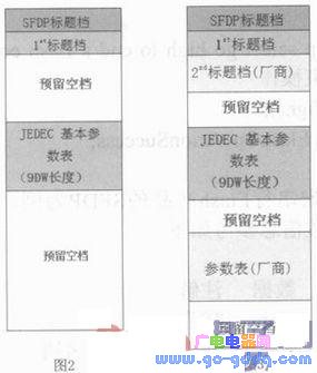
In the function and structure of SFDP, the SFDP standard mandatory specification must have SFDP title file, 1st parameter title file and corresponding JEDEC Flash basic parameter table. The structure is shown in Figure 2. The SFDP title file mainly sets the signature information 0X50444653 ("S", "F", "D", "P" ASCII code) for the developer and the designer to check and confirm. After reading and confirming the signature information, it can be considered. The serial Flash device supports the SFDP standard. In the JEDEC Flash basic parameter table, some of the most basic reading methods, instruction contents, sector size and chip capacity of the device are specified and defined. Secondly, each serial flash manufacturer can increase the 2nd, 3rd parameter header files and corresponding parameter tables in order to expand some parameter characteristics according to the SFDP specification, and enhance the parameter recognition of the device body. The structure is shown in Figure 3. In the vendor header file, the manufacturer's ID identification number, SFDP version number, parameter length, and address pointer for storing the parameter table are serialized and reserved. The parameter table allows the manufacturer to display certain other parameter information such as voltage, special instructions and function support that can be placed in its device, or it can be clearly displayed in the reading, but it is not mandatory by the SFDP standard. , is optional.
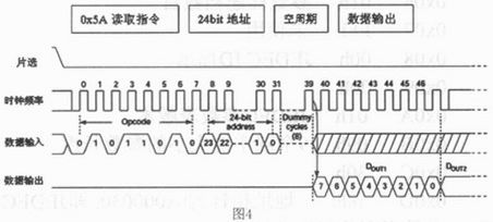
4 Read the operation flow and code system of SFDP on the system software. For any operation of serial flash, the serial flash must be operated correctly in the software according to the corresponding instruction and specification process. Reading SFDP must also follow the prescribed operational procedures. Open the chip select strobe chip ---> send 0x5A read SFDP instructions --> send 3byte address --> send 1 byte empty cycle ---> read SFDP on the output pin Data --——> Close the chip selection end operation. The timing for reading SFDP data by one-in-one method is shown in FIG.
FTTH Drop Cable Patch Cord,Plastic Box With Splitter,Wall Mounted Fiber Terminal Box
ShenZhen JunJin Technology Co.,Ltd , https://www.jjtcl.com