Abstract: Aiming at the situation that the traditional fixed monitoring and erection cost is high, the monitoring has a dead angle and there are too many video acquisition terminals to be arranged, a mobile video surveillance system based on ARM and FPGA combined architecture and its hardware and software implementation method are proposed. Under the premise of reducing the video acquisition end node, it can capture the information required by the user in real time. The system is composed of a motor control module, a video acquisition module and a wireless network control module, and realizes a wireless video monitoring system; based on the Linux operating system, the web server and the video encoder, the user can remotely view the status of the target site through the Internet.
China's video surveillance market is developing rapidly, and digital surveillance has gradually become mainstream. Networking, personalization and intelligence will be an important development trend in China's video surveillance market. However, the current technology based on streaming media has high requirements on network conditions, and cannot be widely promoted. The fixed monitoring cost is too high. How to combine video surveillance with Interne to enable monitoring personnel to implement monitoring anytime and anywhere is an urgent problem for modern surveillance technology. On the other hand, most of the microcontrollers used in video surveillance systems are ARM9, ARM11 and other series of microcontrollers. ARM microcontroller hardware peripherals have been fixed at the factory, which is not conducive to users to expand and upgrade hardware, while ARM and FPGA Combined multi-chip solutions will incur too high a system cost, and will also waste system resources and consume too much power. In view of the above deficiencies, this paper proposes a new solution, using Zynq series processor, the chip is combined with high-performance Cortex-A9 dual-core and FPGA, ARM part can solve HD video processing problem, programmable logic FPGA part You can upgrade and expand your hardware.
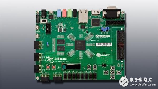
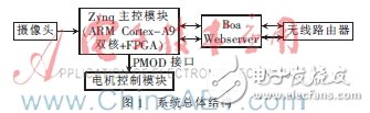
1 Mobile video surveillance system architectureThe main control board of this design is Digilent's ZedBoard development board. The main chip Zynq7020 combines high-performance dual-core ARM Cortex-A9 MPCore processing system and programmable logic [1]. The video capture end is located above the mobile trolley to achieve the purpose of moving the collected video. The design of the system mainly includes the design of the ARM control part and the design of the logic part of the FPGA. The ARM part is mainly used to run the operating system and application software on the system, such as Web server Boa, video encoder mjpg-streamer; FPGA part is mainly used to expand hardware resources, and design the PWM IP core of the car motor drive part. The overall structure of the system is shown in Figure 1. The functions of each module are: the camera is responsible for video image acquisition, the Zynq main control module is responsible for the ARM operating system part and the FPGA logic resource part, the motor control module is responsible for the movement of the smart car, the Boa Webserver is responsible for the network interaction, and the wireless router is responsible for the transmission and reception of the wireless network data. .
After the system is powered on, the chip initialization program that is internally solidified in the chip is automatically executed first, and then the first stage boot loader FSBL is executed, and the FPGA part is configured using the bit stream file (bit file generated by the PWM IP core design), and the FPGA configuration is performed. After the completion, start the U-boot boot program and start the Linux operating system [2]. After the system is started, the smart car generates a wireless signal through the wireless router, and the user can connect the smart car terminal through the network at the other end to implement video surveillance. The interaction between the user and the system is shown in Figure 2.
This paper mainly introduces the design of the motor control part, including the design of the hardware circuit of the motor control part, the design of the PWM part of the FPGA, and the design of the PWM driver of the Linux operating system.
2 Design of the motor control part2.1 Design of the hardware circuit of the motor control part
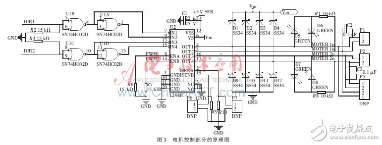
This module is mainly realized by L298P double H-bridge DC motor driver chip. Since one L298P chip can drive two DC motors, the car has four wheels, so two L298P chips are required [3]. At the same time, in order to reduce the number of FPGA I/O pins used, a four-two input or non-gate SN74HC02D is used in the schematic design, so that the four inputs of the L298P can be controlled by two I/O pins. DIR1, DIR2, PWM1, and PWM2 are connected to the FPGA through the PMOD interface of Zedboard. The schematic diagram is shown in Figure 3. In the figure, IN1, IN2, IN3, and IN4 are input signals, and ENA and ENB are enable signals. ENA controls the input enable of IN1 and IN2, and ENB controls the input enable of IN3 and IN4. When ENA is 1, and DIR1 is 1 (that is, when IN1 is 0 and IN2 is 1), the motor on the P1 interface is rotating forward; when ENA is 1, and DIR1 is 0 (that is, IN1 is 1, and IN2 is 0). ), the motor on the P1 interface is reversed; when ENA is 0, the motor on the P1 interface is stopped. The principle of the motor connected to the P2 port is the same as above.
2.2 FPGA part PWM IP core design
The Xilinx embedded system part is designed by the company's EDK (Embedded Development Kit) development kit. EDK has a complete set of tools for embedded system design: hardware design tool XPS (Xilinx Platform Studio) and software design tool SDK (Xilinx Software Development Kit), the hardware design steps are as follows: (1) set up a new project path;
(2) Custom IP configuration peripherals;
(3) Establish a UCF file;
(4) Generation of bit stream [4]. The part of the custom IP mainly implements the forward, reverse and stop control of the motor. The key VerilogHDL code is as follows:
Case(state)
//The motor stops
'NOP:{pwm_left,pwm_right}<={7'd0,7'd0};
'GOING: motor forward rotation
Begin
If(dis_value>31)
{pwm_left,pwm_right,dir_lself,dir_rself}
<={7'd100,7'd100,1'd0,1'd0};
Else
{pwm_left,pwm_right,dir_lself,dir_rself}<=
{{dis_value[4:0], 2'b0}, {dis_value[4:0], 2'b0}, 1'd1, 1'd1};
End
'RETURN://motor reverse rotation
Begin
If(dir_value==3'b010)
{pwm_left,pwm_right,dir_lself,dir_rself}<={7'd80,7'd80,1'd1,1'd0};
Else
{pwm_left,pwm_right,dir_lself,dir_rself}<={7'd80,7'd80,1'b0,1'b1};
End
Endcase
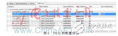
In this design, the control of the motor, the amount of data transferred is small, only need to add a low-speed AXI4-Lite bus device PWM module to control the PMOD interface to achieve communication between hardware devices, of which AXI4-Lite global time The ACLK is set to 100 MHz, the starting physical address of the PWM module is 0x6CA00000, and the space size is 64 KB. The PWM configuration information is shown in Figure 4.
2.3 Design of the motor drive part under Linux
Since the remote transmission is implemented under the TCP/IP protocol under Linux system, the IP driver under Linux can be written, and the application can access the PMOD interface device of the FPGA through the standard interface of Linux. This design is written as a character device driver that includes device loading, device unloading, and file manipulation functions. When the PWM module is loaded, the system calls the module_init(pwm_init) macro to realize the initialization operation of the module. In this system, the pwm_init() function mainly performs the following tasks: (1) the kernel registers the character device driver; (2) creates the PWM device class; (3) Use the PWM device class to create the device; (4) map the physical address of the PWM module to the virtual address [5]. Some of the key codes are as follows:
//XPS assigned physical address
#define PWM_MOUDLE_PHY_ADDR 0x6CA00000
//Register driver
Pwm_driver_major=register_chrdev(0,DEVICE_NAME,&pwm_driver_fops);
Pwm_driver_class=class_create(THIS_MODULE,"
Pwm_driver");//Create device class
Pwm_driver_device=device_create(pwm_driver_class, NULL, MKDEV(pwm_driver_major,0), NULL,"pwm_device");
/ / Use the device class to create a device
/ / Map the PWM IP physical address to a virtual address
Pwm_fre_addr=(unsignedlong)ioremap(PWM_MOUDLE_ PHY_ADDR, sizeof(u32));
The initialization is over, but only the initialization function, the device still does not work, and there is a need to adjust the frequency and duty cycle. The frequency function that controls the PWM is as follows:
staTIc ssize_t sys_pwm_frequency_set(struct device*dev, struct device_attribute*attr, const char*buf,size_t count)
{
Long value=0;
Int i;
Frequency=0;
/ / Change the frequency, close the PWM module
Outl(value,pwm_fre_addr);
/ / Convert the string written to pwm_frequency into an integer
For(i=0;i100000000)value=100000000;
Value=100000000/frequency;
/ / Write the count value to the pwm_fre_addr register of the PWM module
Outl(value,pwm_fre_addr);
Return count;
}
The function that controls the PWM duty cycle is the same as the function that controls the PWM frequency.
3 Experimental results and testingThe main control board of the system is the Zedboard development board. After the power is turned on, the wireless router will release a wireless network with the SSID Tp_Link_5C90, which can be connected to the network through any device that can access the Internet. Enter the URL: 192.168.1.100 in the browser, you will log in to the mobile video monitoring web page, and control the operation of the video terminal through the buttons on the interface.
This paper uses Xilinx All Programmable chip Zynq as the main control CPU. The FPGA part can realize logic expansion and function supplement. For example: custom communication protocol, IP core, and also can use Xilinx's partial reconfigurable technology to upgrade the hardware system, easy to extend and hardware upgrade; ARM part uses the higher performance Cortex-A9 dual core, making high definition The processing of the video is smooth, and the overall function of the system is relatively stable. Compared to traditional analog monitoring, digital video processing technology improves image quality and monitoring efficiency.
The software and hardware collaborative design method is adopted in the design, that is, the software and hardware are designed and coordinated on the basis of the whole system and definition, including the division of hardware and software (what functions are completed by software and which functions are completed by hardware), The development and joint debugging of software and hardware systems reduces development risks and shortens the development cycle.
references
[1] Xilinx Inc. UG585, Zynq-7000 All Programmable SoC Technical Reference Mannual[Z]. 2013.
[2] Xilinx Inc. UG873, Zynq-7000 All Programmable SoC: Concepts, Tools and Techniques[Z]. 2013:12-35,40-53.
[3] Wang Fangfang, Zhang Huan. Design of Dynamic Smart Home System Based on Zynq Platform[J]. Software, 2013, 34(8): 98-100.
[4] Hu Dianrong, Guo Chunsheng. Design of SPI and Ethernet Transmission Based on ZedBoard[J].Journal of Hangzhou Dianzi University,2013,33(5):126-129.
[5] Lu Jiahua, Jiang Zhou, Ma Wei. Collaborative Design Guide for Embedded Systems Software and Hardware: Based on Xilinx Zynq [M]. Beijing: Mechanical Industry Press, 2013.
12v power supply is suitable for LED, Electronic cigarette, Tablet, Water purifier, Router, CCTV camera, LCD, Motor, Fan, Toys Medical machine, POS machine, Beauty & Health equipment, Humidifier, LED lights etc.
We can meet your specific requirement of the products, like label design. The plug type is US/UK/AU/EU. The material of this product is PC+ABS. All condition of our product is 100% brand new. You can send more details of this product, so that we can offer best service to you!
12V Power Supply,12V Pc Power Supply,12V Dc Power Supply ,12V Power Supply For Pc
Shenzhen Waweis Technology Co., Ltd. , https://www.waweis.com