Abstract : MicroBlaze soft core is used as the hardware platform of CPU. On this platform, a universal real-time clock IP core based on AXI bus is designed. The process of creating an IP core and the method of importing an IP core are given. The IP core structure of the real-time clock is introduced, and the block diagram of the IP core is given. The principle of real-time clock is introduced, and the core code of each module of real-time clock is given.
introductionMicroBlaze is a soft core of RISC processor that can be embedded in FPGA. It has the advantages of fast operation, low resource consumption and strong configurability. It is widely used in communications, military, high-end consumer markets and other fields. Xilinx's MicroBlaze 32-bit soft processor core is a collection of standard peripherals that support the CoreConnect bus. Operating at 150 MHz, the MicroBlaze processor is ideal for designing complex embedded systems for the networking, telecommunications, datacom, and consumer markets.
AXI is the most important part of the AMBA 3.0 protocol proposed by ARM. It is an on-chip bus for high performance, high bandwidth and low latency. AXI bus technology not only enables the on-chip system to be smaller and consumes less power, but also achieves superior performance. One of the main reasons AXI can achieve such a specification is its one-way channel architecture. The unidirectional channel architecture allows the on-chip traffic to be transmitted in only one direction, reducing latency. AXI technology meets the needs of ultra-high performance and complex system-on-chip design, so AXI is becoming more and more widely used [1]. As the cooperation between ARM and Xilinx has gradually strengthened, Xilinx has gradually promoted AXI bus technology in FPGA products. AXI is getting more and more important support on CPUs such as Xilinx's MicroBalze, and it will become the mainstream technology in the future.

Xilinx's MicroBlaze soft core provides users with a large number of available IP cores, which is convenient for users to develop and shorten development cycles and reduce costs. However, the needs of users vary widely, and the IP core provided by the official website cannot meet the needs of all. Therefore, the development environment supports user-defined IP cores. According to the different needs of users, users can develop their own IP cores through customized methods. In the development process of the measurement and control device, the author found that the RTC clock chip designed on the plug-in has the function of power-down retention time. However, when the function of the device interface is completed, the read and write operation of the RTC chip is displayed on the interface, and there is a certain delay, and the interface cannot accurately display the current time. Therefore, designing a real-time clock clock function through the form of a custom IP core solves the above problem. Xilinx Platform Studio in the development environment provides wizards for the valuation and import of IP cores.
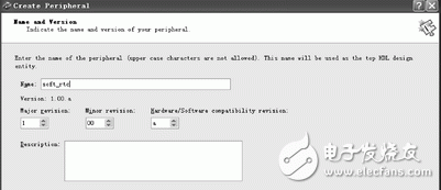
To create an IP core, follow these steps: Select Hardware→Create or Import Peripheral Wizward to open the Create and Import Peripherals wizard. Click the Next button. Choose Create templates for a new peripheral. By default new peripherals will be stored in the pcores folder for easy searching. Then click the Next button again. In the Create PeripheralName and Version dialog box, enter the name of the custom IP core. Enter the custom IP core name as soft_rtc. Below is the version control, which can be modified as needed. The interface is shown in Figure 1.
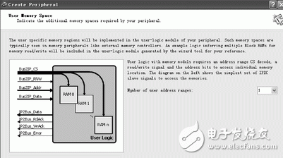
Click the Next button and in the Create PeripheralBus Interface dialog, select AXI4, which is the bus to which the new peripheral will be connected. For simple design, you can choose AXI4_Lite; the next step is in IPIF (IP interface) configuration, here configure some properties of the interface, such as whether it is AXI master/slave device. The customized IP is a slave device and thus does not require the use of a master device interface. The data width is selected as the default 32 bits. The next step is to select the number of use memory ranges. The interface is shown in Figure 2.
Next is the IPIC (IP Interconnect), which is the interface signal of the IP. Next, you need to use the BFM bus function model to simulate the peripherals. Do not use this example. Finally, you need to choose the HDL type, ISE engineering support, and software driver templates. The Verilog template is used here. After selecting, the IP interface is still written in VHDL, but the user logic is changed to Verilog. If you do not need to use a software driver template, you can choose not to. Finally, the information summary of the peripheral is given. After completing the above steps, the template of the customized soft_rtc IP core is created, and the application code is simply written according to the requirements of the user_logic file, and the corresponding pins are configured.
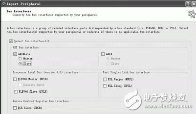
After the user_logic code is written, the completed IP core needs to be imported into the project. The general steps are as follows: Use Hardware Create or Import Peripheral again, and click the Next button. Select the Import exisTIng peripheral item, click the Next button to enter the name soft_rtc again, click the Next button, and select the Yes button. Next select the first HDL source files and click the Next button. Then select the second item Use exisTIng Peripheral Analysis Order files(*pao) in the next step, browse to the corresponding directory, select the .pao file, click Open, and then Click the Next button; when the window shown in Figure 3 appears, select the left AXI4Lite option, then click the Next button to select the default option until the end window is displayed and select the Finish button Finish button. In this way, the creation and import of the IP core is completed through the above steps. Finally, the IP core is added to the project and connected to the AXI4Lite bus. After completing the creation and import of the IP core template, the next step is to complete the code design of the IP core user_logic file.
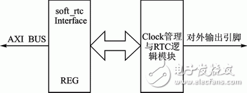
The soft_rtc IP core is mainly divided into a register management module with an upper interface, a clock frequency division module that provides an accurate clock for the IP core, and a core logic module of the RTC [2]. The IP core interface is shown in Figure 4.
A 25 MHz crystal and a 16.384 MHz crystal are provided on the development board. For timing accuracy, the 16.384 MHz input signal is introduced into the soft_rtc module. The Clock divider module divides the input 16.384 MHz quasi-crystal oscillator clock by 4 to get a 4.096 MHz clock signal. The crossover core code is as follows:
Always @(posedge clk_in)
Begin
If(clk_div == 4'b0011)
Clk_div <= 4'b0110;
Else if(clk_div == 4'b0110)
Clk_div <= 4'b1100;
Else if(clk_div == 4'b1100)
Clk_div <= 4'b1001;
Else
Clk_div <= 4'b0011;
End
The main function of the register control module is to implement read and write control of each register inside the RTC module and provide control signals for the entire IP module. Provides an interface between the upper application code and the IP core code. Inside this module are included sub-modules that control the read and write of each internal function register and the overall distribution control of the clocks of each sub-module [3]. A total of 16 registers are defined in this design, including control register, status register, and millisecond read register, millisecond write register; second read register, second bit write register, quantile read register, quantile write register, The hourly read register, the hourly write register, and the year, month, and day read and write registers.
Set the RTC core code as follows:
Always @(posedge Bus2IP_Clk)
Begin
If(Bus2IP_CS[0] && Bus2IP_WrCE[0] && (Bus2IP_Addr[9:2] == SETSECOND_Addr)
SetSecondRegister <= Bus2IP_Data[5:0];
......
End
Read the RTC core code as follows:
Assign IP2Bus_Data[15:0] = (Bus2IP_CS[0] && Bus2IP_RdCE[0] && (Bus2IP_Addr[9:2] == MSECOND_Addr))?{6'h00,GetMsecondRegister}:16'hzzzz;
......
The main function of RTC's core logic module is accurate timing. Through the control of the counter in the IP core, the milliseconds are 1000 rounds, the seconds, minutes and hours are 60 rounds, and the month is 12 rounds. The design should be fully considered in the actual situation, pay attention to the treatment of different situations such as leap years and different months. The core code for RTC timing is as follows:
Always @(posedge SETTIME or posedge clk_jg)
Begin
If(SETTIME)
SecondRegister <= SetSecondRegister;
Else if((SecondRegister_B < 59) && Msecond_Carry)
SecondRegister <= SecondRegister + 1;
Else if(Msecond_Carry)
SecondRegister <= 6'h00;
Else
SecondRegister <= SecondRegister;
End
......
When the rising edge of the clock arrives or the application sends a set time command, it is judged: if the second bit is less than 59 and the millisecond bit has a carry, then the second bit counter is incremented by one; if the second bit counter is greater than or equal to 59, the millisecond bit has a carry Clear the second bit. In other cases, the second counter keeps the original value. Other counts, hours, days, months, and so on are counted by analogy.
Conclusion
In the soft_rtc IP core application, the hardware RTC chip time in the device is first read, and the soft_rtc IP core of the design is subsequently written after the current time is acquired, so that the soft_rtc time is synchronized with the hardware RTC time. During the operation of the latter device, both the protection event upload and the recording event uploading and other time-related reading and writing operations are completed by the soft_rtc IP core. It avoids repeated operations on the hardware RTC chip, improves stability, and saves system resources. After the design is completed, it can be printed through the serial port, or the time information can be uploaded to the device interface display through the communication frame, and the time is accurate and reliable. This soft_rtc IP core is easy to port and can be extended to subsequent products.
references
[1] Tian Ze, Cao Qingnian, Liu Tianshi, et al. Design and implementation of RTC module for embedded processor S3C2440 Windows CE[J]. Computer Applications and Software, 2007, 24(3): 3133.
[2] Zhou Wei, Xie Xiaoyang. Analysis and Application of Finite State Machine in RTC Design[J]. Computer Systems, 2008, 17(5): 7780.
[3] Yan Zhanfeng. Application Research of RTC Technology in System Integration[J].Information Communication,2012(6):3738.
Saqizhina (engineer), engaged in power grid automation research.
LED Troffer driver
Fahold, a 8 year old company brings light power to your life by illuminating your offices, factories, warehouses, shopping malls, airports, etc. with its high quality LED Troffer lighting products and solutions.With global manufacturing standards and various certifications including CE,TUV, UL and FCC, our lighting products are sold in domestic market and are exported to various international markets including US, UK, France, Germany, Australia, Africa, Korea etc. We offer a wide range of Lighting source for LED lighting solutions which includes LED TrofferLighting or System, , LED Lams, LED Panel etc. At the same time Maximize beauty of your workplace with our powerful driver to drive Warehouse Lighting, Workshop Lighting, Supermarket Lighting and Factory lighting solutions. We have skilled engineers to answer all your questions and enquiries and provide all-round solutions basis on your project(s) and provide technical supporting.
Application: Specifically for led Troffer light,AC100-277V/347V,1-1.5A output current,Iron box casing, support 0-10V/PWM/RX dimming, High efficiency and PF value, Pass the UL/FCC/Class P certified for North America market.
Parameter:
Input voltage:100-277V
Output voltage:25-40V
Current:1100mA/1500mA
PF:>0.9
THD:<15%
Size style: Iron box, long slimline.
Dimming:0-10V / PWM / RX / DALI.
>=50000hours, 3-5 years warranty.
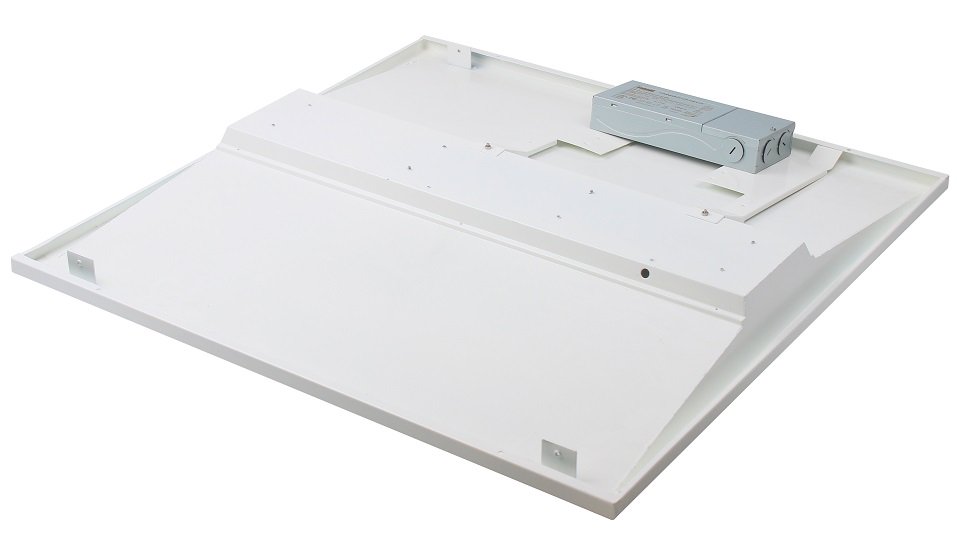
What's the benefits of Fahold led Troffer lights driver?
- Standard Linear Lighting
- Cost-effective light-line solution for industry,commercial and other applications
- Good quality of light with high lumen output to meet different requirements
- Easy to order and install,requiring less time,reducing packaging waste and complexity
- Flexible solution
FAQ:
Question 1:Are you a factory or a trading company?
Answer: We are a factory.
Question 2: Payment term?
Answer: 30% TT deposit + 70% TT before shipment,50% TT deposit + 50% LC balance, Flexible payment
can be negotiated.
Question 3: What's the main business of Fahold?
Answer: Fahold focused on LED controllers and dimmers from 2010. We have 28 engineers who dedicated themselves to researching and developing LED controlling and dimming system.
Question 4: What Fahold will do if we have problems after receiving your products?
Answer: Our products have been strictly inspected before shipping. Once you receive the products you are not satisfied, please feel free to contact us in time, we will do our best to solve any of your problems with our good after-sale service.
600X600 Panel Light Driver,5Years Warranty Driver,Junction Box Driver
ShenZhen Fahold Electronic Limited , https://www.fahold.net