The power supply sequence is an important consideration when designing a field programmable gate array (FPGA). Since design requirements may range from three tracks to more than ten tracks, FPGA vendors typically specify power supply sequence requirements. If you follow the recommended power sequence, you can avoid excessive power generation during startup and avoid damage to the unit. There are several ways to achieve the power supply sequence in the system. This article will explain the various sequence solutions that can be adopted according to the complexity of the system requirements.
Sequence Solutions Improve FPGA Energy Efficiency
The sequence solutions described in this article include:
1. Connect the PGOOD pin as a boot pin
2. Use the reset chip row
3. Analog power recovery / cut sequencer
4. Digital System Health Monitor with Power Management Bus (PMBus) Interface
Method 1: Connect the PGOOD pin as a start pin. To sort in a basic and cost-effective manner, connect the PG pin of a power supply as the start pin for the next sequence power supply (Figure 1). After reaching the PG threshold (usually the power supply reaches 90% of the final value), the second power will be activated. This method is cheaper, but it is not easy to control the time. If the capacitor is added to the EN pin, the time difference can be added between the levels. However, this method is not reliable when the temperature changes and the power supply is repeatedly cycled. In addition, this mode does not support the power-off sequence.
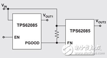
Figure 1 Connect the PGOOD pin as a boot pin
Method 2: Using Reset Chip Sorting For power recovery sequencing, another easy way is to reset the chip and time difference. Resetting the chip monitoring threshold limits the tight power rail. Once the power rail is only 3% or less from the final value, the reset chip will enter the waiting period set by the solution and then start the next rail. As long as the EEPROM or external capacitors are used, the wait period can be included in the reset chip programming. Generally, the multi-channel reset chip (Fig. 2) can be used to monitor the solution by using the reset chip when the power is restored.
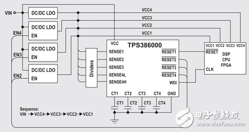
Figure 2 resetting the chip with multiple outputs to achieve power recovery sequencing
Since the system will determine that each rail remains within the regulation range, the next rail will be activated, so the transformer does not need to have a PGOOD pin, but the reset chip sequence solution is not suitable for power-off sequencing.
Method 3: Analog Power Recovery/Shutdown Sequencer Power recovery ordering is usually simpler than power-off sequencing. To achieve both, use a simple analog sequencer (Figure 3), flip (sequence one) or mix (sequence two) relative In the power-off sequence of the power recovery sequence, when the power is restored, all flags will remain low before the EN rises. After the EN reaches the standard, each flag passes through the open-drain as the internal frequency passes. resistance). The power cut sequence is the same as the power recovery, but in reverse order.
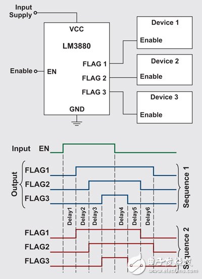
Figure 3 analog power recovery / cut sequencer
. Serializing multiple sequencer sequencers in series supports a number of power rails and provides a fixed or adjustable delay between the Enable signals. In Figure 4, the two sequencers are concatenated together. In order to build six sequence tracks, when the power is restored, the second sequencer will only start when the AND gate receives the EN signal and the C track is activated. When the power is turned off, the AND gate ensures that regardless of the C output, the second The sequencer will see the EN negative edge. The OR gate ensures that the first sequencer starts with the EN positive edge. When the power is turned off, the OR gate ensures that the first sequencer will not see the EN negative edge before D is lowered. This will achieve a power recovery and power-off sequence. However, no monitoring sequence was provided.
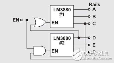
Figure 4 serially connecting multiple analog sequencers
. Monitoring Power Recovery/Disconnection Sorting As long as several AND gates are added between the FlagX output of Figure 5 and the PG pin, the monitoring order can be added to the line of Figure 4. In this case, PS1 must exceed 90% of the final value, PS2 will start, so that a low-cost monitoring and sorting solution can be achieved.
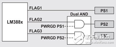
Figure 5 Adding monitoring sorting to the simple frequency sequencer
Method 4: Digital System Health Monitor with PMBus Interface
If the system requires maximum flexibility, the PMBus/I2C compatible digital system health monitor is very suitable. With the UCD90120A as an example, the designer can configure the ramp up/down time, switch delay, sequence dependency, current and voltage monitoring, etc. Maximum sequence control requirements.
The Digital System Health Monitor, when combined with the Image Usage Interface (GUI), can be used with other system parameters to program power recovery/disconnection sequences (Figure 6). Some digital system health monitors also feature non-volatile error and peak recording. Assist system failure analysis in case of weak power supply.
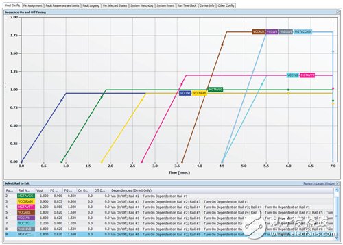
Figure 6 Example of a power recovery sequence using the UCD 90120A GUI
FPGA vendors such as Xilinx provide recommendations or necessary power recovery sequences in the product manual. Users can obtain them from the Internet. The serial requirements of each manufacturer are different, even for the same manufacturer, different FPGA series products. The requirements vary, and the product specification also lists the point-in-time requirements for ramp up and shutdown, while the recommended power-off sequence is usually the reverse of the power-recovery sequence. Figure 7 shows an example of a power recovery sequence.
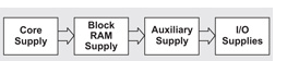
Figure 7 FPGA power logic sequence example
Multiple sequence solutions can be combined with the requirements of FPGA vendors. In addition to power recovery and power-off sequences, system requirements may also include power supply monitoring, but the optimal FPGA power solution still depends on system complexity and specifications.
LED flag screen totem on light poles or Outdoor led screen kiosk, can save installation cost and time by pulling down and updating the printing advertising for light box. you can also unified management of intelligent management system. advertising can be really controlled,The Outdoor flat screen Is expected to become a large-scale media after as new carrier of advertising.
Small body, big world, It is not only small pixel pitch for led display, but a small era of led screen!
The flag LED display kiosk on each road poles, not only can realize the comprehensive utilization of road poles, making the road no longer monotonous, but also can play content according to different festivals and beauty the city. At the same time, it will also provide the public with weather changes, environmental pollution and road access. bring more convenience to the public.
Priva provides professional intelligent Led light pole screen solutions and professional commercial LED display technology With a wealth of LED project engineering experience, Priva Led will meet customer`s varity needs.
Integrated design, easy to use
Operate controller inside, Optional of installation on back column and side of pole, Easy to transport & install.
Intelligent management and Large scale cluster control and management. easy and convenient
Managing multiple displays via cable, 3G, 4G, WAN and LAN; Could manage by mobile phone with APP. 1-1 and 1-N management One click to release, timing, updating AD.
Outdoor Led Flag Screen Totem,Outdoor Led Flag Screen,Outdoor Flag Screen,Slim Outdoor Led Poster
Shenzhen Priva Tech Co., Ltd. , https://www.privaled.com