0 Preface
In recent years, with the rapid development of LED technology, LED applications have entered a new era of prosperity. As an indispensable part of LED application, driving technology has attracted more and more attention [1]. The characteristics of LED-like diodes such as volt-ampere characteristics, long life, high luminous efficiency, and strong controllability put forward some new requirements for traditional switching power supplies for driving power supplies [2]. In this paper, we will introduce some new developments in the industry from the aspects of topology, reliability and controllability of the driving power supply.
1 New research on LED drive topology
LED as a solid-state light source, its diode-like electrical characteristics determine the need to use a constant current circuit to drive it. The quality of the drive circuit directly affects the efficiency and life of the entire light source system. Therefore, the development and improvement of LED driver circuits is a key direction in the industry. The drive circuit input can be DC or AC. Here we mainly discuss the research progress of the AC input, ie the offline drive.
1.1 Offline Switch Driver Research
The off-line switch driver refers to a switching power supply that obtains voltage from the AC grid and drives the LED load, which generally has the advantages of high efficiency and electrical isolation. Topologically classified, it can be divided into Forward, Flyback, Half Bridge, Full Bridge, and LLC Resonant Half Bridge. Wait. At present, the widely used off-line LED switch drivers on the market mainly use flyback and half-bridge LLC resonant modes. Among them, the flyback topology is favored by small and medium power applications due to its simple circuit, low cost and high efficiency. The half-bridge LLC resonant topology is used on high-power LED drivers on a large scale with very high efficiency and power density, good output characteristics and electromagnetic compatibility.
In view of the improvement of existing topology, the research hotspots mainly focus on efficiency, power factor improvement and structure simplification.
The flyback driver transmits energy through the transformer. Since the original secondary winding is not fully coupled, the energy on the leakage inductance cannot be effectively transmitted, resulting in loss. A literature [3] proposes a relatively new and practical solution. By integrating the buck-boost circuit with the flyback circuit, the buck-boost circuit ensures a high power factor, and the loop leakage energy is improved. effectiveness. Since the leakage inductance energy is absorbed, the voltage stress at the time when the switch tube is turned off is further reduced, which is a three-pronged one. The application of 8W for 265V input achieves a power factor of 0.95 and an efficiency of 90%.
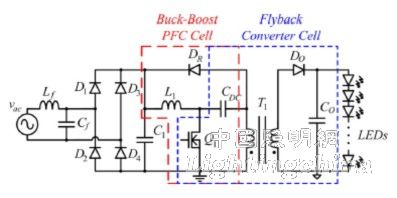
Figure 1 Schematic diagram of recycling leakage inductance energy to achieve high efficiency and high power factor
The literature [4] also uses the buck-boost circuit for power factor correction. It achieves efficiency improvement through a two-stage structure combined with zero-voltage switching technology. The power factor of 0.99 and 93% efficiency are achieved for 60W applications.
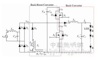
Figure 2 Schematic diagram of zero-voltage switching high efficiency and high power factor circuit
In addition, as an important part of electromagnetic compatibility, the realization of high power factor is also a research hotspot [5], related innovative control methods and structural research emerge in an endless stream [6][7][8], for the flyback driver to achieve power Factor correction provides a broader solution.
In traditional isolated flyback driver applications, optocouplers have been used as electrical isolation and signal feedback for the primary and secondary sides. In recent years, many related researches have focused on how to implement primary side control, thereby eliminating optocoupler, reducing drive volume, reducing cost, and improving reliability, thus showing advantages in low power applications [9][10][11 ].
For topological structures such as half bridges, some scholars have analyzed and compared existing topologies [12]. In [13], an asymmetric half-bridge structure is proposed and analyzed. On the one hand, by the asymmetric design of the secondary winding of the transformer, the average value of the excitation current is reduced, thereby reducing the conduction loss. On the other hand, the zero-voltage switching technology reduces the switching losses of the switching transistors and diodes, thus achieving higher efficiency. On this basis, some other literatures have carried out related research work [14][15].

Figure 3 Asymmetric Half-Bridge Topology for Reducing the Average Value of Transformer Excitation Current
In the new topology research of LED driver applications, J. Marcos Alonso et al. proposed a novel dual buck-boost (IDBB) topology [16] [17]. The cascaded buck-boost circuit is controlled by a single switch to operate the DCM and CCM modes, respectively, resulting in higher power factor and smaller output capacitance. However, due to the large loss of energy in multiple transfers, the system efficiency is not high. Douglas Camponogara et al. have made some improvements on this basis, and proposed an optimized cascading method, which reduces the energy ratio after two transfers, thus improving the system efficiency [18]. The optimized system achieves 94% efficiency at 75W load, which is a significant improvement over the original 85% efficiency.
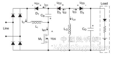
Figure 4 IDBB type driver circuit schematic

Figure 5 An improved IDBB drive schematic
1.2 Non-switching driver research
In order to avoid the use of complex switching circuits, thereby reducing costs and improving system reliability, direct driving of LEDs with AC power is also a hot research topic. There are also related literatures on the characteristics of LEDs driven by AC [19].
Traditional AC direct drive LEDs are often used in two ways. One is to use two sets of LEDs in reverse parallel. The two sets of chips work in the positive and negative half cycles of the alternating current. The other is half-wave rectified and connected to the LED load through the rectifier bridge. . The load regulation rate of these two circuits is poor. Due to the short LED conduction time, there are generally problems such as low power factor, stroboscopic, and thyristor dimming. The former is only a half cycle of each group of LEDs. Faced with higher cost issues.
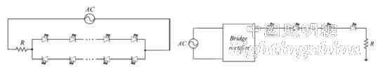
Figure 6 Two ways of traditional AC direct drive LED
Through the AC-DC LED design of the bridge rectification structure [20], most LED chips can be put into operation, which improves the utilization rate of the LED chip. Combined with the use of a constant current diode, limiting the LED current can further improve the reliability of the system.
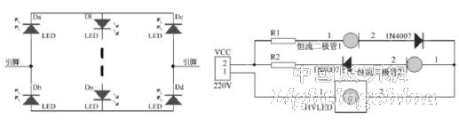
Figure 7 AC/DC LED application of a bridge rectifier with a constant current diode
Segmented LED control is a relatively new and effective technology, which can greatly improve the LED on-time, short harmonic content, low power factor and other issues in AC LED applications. There are related mature driver products [21]. In [22], an FPGA-based segmented AC LED control method is proposed. By detecting the line voltage of the AC power supply terminal, the number of LEDs that are turned on in the LED load is controlled, and the conduction angle is extended to simulate the resistance load characteristic. In order to achieve the purpose of reducing harmonics and improving power factor, it is better compatible with thyristor dimming.
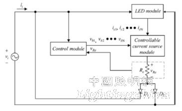
Figure 8 Block diagram of the segmented AC LED control structure
In addition, passive resonant LED driver [23], switch chopper-linear constant current driver [24] and other drivers have their own characteristics, the former through the design of the resonant network, on the basis of ensuring a constant average current, High efficiency and reliability; the latter achieves constant current drive at low cost, and both have certain practicability.
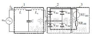
Figure 9 Schematic diagram of passive resonant LED driver
For the stroboscopic problem that AC LED 50Hz or 100Hz voltage cycle may bring, an effective method is to use long-lasting phosphor at the LED device level, which can compensate for the LED chip not emitting light when the AC cycle changes. The resulting luminescence discontinuity solves the stroboscopic radiance [25].
2 LED drive reliability related research
Another major feature of LED light sources is their long life, which requires LED drivers to ensure system reliability as much as possible and achieve high MTBF.
2.1 Electroless Capacitor Drive Research
Electrolytic capacitors are typically used to drive input energy storage, balance instantaneous power, and output filtering. Because of its relatively short life, how to improve the circuit structure, reduce or even eliminate the use of electrolytic capacitors has become a hot research direction in the field of LED driving. The following is a brief list of recent research advances.
Early studies mostly focused on harmonic injection and pulsating current output [26], which have an impact on power factor and output current, and have certain limitations. A method is proposed in [27] to increase the voltage ripple on the storage capacitor and ensure a constant current output while achieving a high power factor.
Shu Wang et al. proposed an active filter circuit [28], which prevents the high-order current harmonics generated by the switch from flowing into the LED through the CL filter on the one hand, and the buffer distribution of the current through the bidirectional converter on the other hand, so that the LED load Only the DC component flows through, so that the flicker problem caused by the pulsating current is avoided without using the electrolytic capacitor. On this basis, Yang Yang et al. proposed a feedforward control strategy based on current reference [29], combined with the output of the current regulator and the current reference feedforward in the double closed loop to calculate the ideal duty cycle of the bidirectional converter. The input current is twice the AC current of the input frequency to avoid stroboscopic distortion caused by LED drive current distortion.
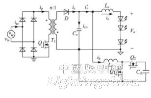
Figure 10 Schematic diagram of active filter type electroless capacitor circuit
Ma Hongbo et al. proposed an improved scheme for electroless capacitors based on SEPIC circuit [30]. The output ripple value was reduced by increasing the ripple method, and the valley filling circuit and current interrupt mode were introduced into the SEPIC circuit. [31], power balancing is achieved by an intermediate capacitor, thereby reducing the required output capacitance. The use of the characteristics of the valley filling circuit reduces the voltage stress of the intermediate capacitor and the diode.
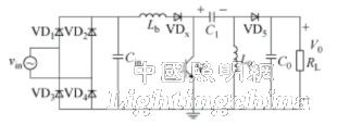
Figure 11 Schematic diagram of the electroless capacitor scheme based on SEPIC circuit
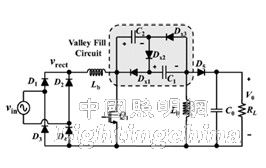
Figure 12 Schematic diagram of SEPIC type electroless capacitor solution with valley filling circuit