Abstract: With the rapid development of electronic technology, embedded systems have been initially applied in the industrial field. According to the needs of the industry, combined with the actual situation, we have selected and optimized various methods, and proposed a motor control and diagnostic scheme based on Ethernet. The specific implementation process is described. The Ethernet-based motor control and diagnostic system uses the C8051F020 microcontroller as the core control device of the system. It is physically connected to the Internet through the RTL8019AS network card, and the streamlined and optimized TCP / IP protocol is embedded in the C8051F020 microcontroller. SPWM is generated by the microcontroller itself Pulse, control the frequency converter, realize the speed control of the motor, and through the parameter collection, the online fault diagnosis of the motor can be effectively performed.
introduction
The control and diagnosis of the single-chip device based on Ethernet combines advanced WEB technology and embedded technology to realize the direct cross-platform information interaction between the PC and the device, so that the PC can share the information of the device operation and effectively control the device And diagnosis.
1 Structure design of motor control and diagnosis based on Ethernet
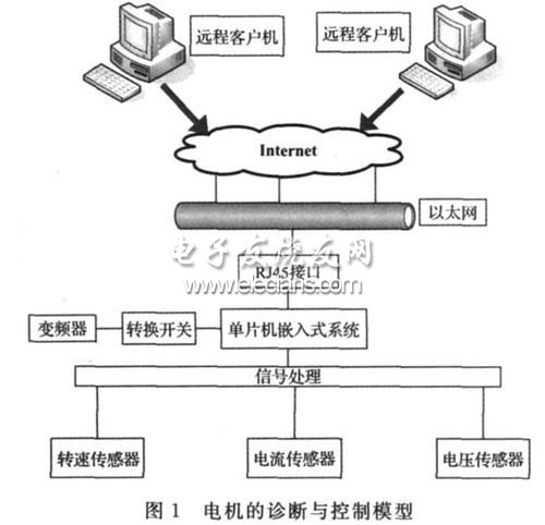
The control and diagnosis of the single-chip device based on Ethernet is based on the research of three-phase motors in the industrial field, including the measurement and control of the motor's running speed, the collection of armature current, the collection of motor potential parameters, and other analog-related quasi-quantities. collection. The main structure of this design is the combination of WEB technology, single chip microcomputer and client, to establish the diagnosis and control model of the motor equipment. The model is shown in Figure 1. The model is mainly composed of the client, the network and the bottom layer of the process control, that is, the embedded system of the single-chip microcomputer. Here, the TCP / IP protocol is used as the communication protocol of the embedded system. The WEB server of the embedded system interacts with the WEB server of the client to upload information The parameters of the motor operation, so that customers or manufacturers can realize the control and online diagnosis of the motor through the network.
2 Realization of the system hardware circuit
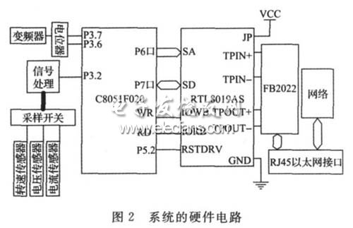
The Ethernet-based motor control and diagnostic system uses C8051F020 microcontroller as the CPU of the embedded system, embeds TCP / IP protocol, and uses RTL8019AS as the network communication chip. It collects motor parameters and controls the speed of the motor by controlling the sampling switch, and passes the RTL8019AS network card. Upload the collected temperature data, speed data, current data, vibration data, and magnetic field data to the server. The client realizes the data sharing through the interaction between the servers. The client uses the single chip to generate SPWM according to the specific needs. 0 ~ 10V or 4 ~ 20mA signal is input to the analog input terminal of the controller, and the output frequency of the inverter is controlled by changing the size of the input analog quantity to adjust the inverter, control the motor speed, and monitor the operation of the motor and diagnose the motor according to the value of the motor parameter The fault, the hardware circuit block diagram shown in Figure 2.
3 Ethernet frame format
There are two kinds of Ethernet protocols, one is IEEE802.2 / IEEE802.3; the other is the encapsulation format of Ethernet. Modern operating systems can support these two types of protocol formats at the same time, so for us only need to understand one of them is enough, especially for single-chip, it is impossible to support too many protocol formats. This system uses the IEEE802.3 Ethernet protocol. Table 1 shows the encapsulation form of the Ethernet frame format.
Table 1 Encapsulation form of Ethernet frame format
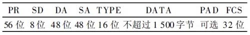
PR: synchronization bit.
SD: Separator.
DA: Destination address. The Ethernet address is a 48-bit (6 bytes) binary address, indicating to which network card the frame is transmitted.
SA: The source address, 48 ​​bits, indicates which network card sent the data of the frame, that is, the network card address of the sending end, which is also 6 bytes.
TYPE: The type field indicates what type of data the frame is.
DATA: data segment, the data of this segment cannot exceed 1500 bytes.
FCS: 32-bit data check digit.
4 System software design
The implementation of the system software includes the initialization of the system clock, timer, network card RTL8019AS, initialization of ARP protocol, TCP protocol and HTTP protocol to complete the reception and transmission of motor parameters, and then the main program loops to query rtl8019as to see if there are new data packets arrival. The system reads the parameters of the motor according to the flag of the judgment event, as shown in Figure 3. The judgment execution of the event is completed by the timer interrupt of the single-chip computer, which runs through the beginning and the end of the program. If the TCP sequence number increases by 6250 every 20ms, the retransmission request during ARP address resolution is retransmitted once every 0.5s. If the retransmission request is not responded for 2 consecutive times, the retransmission is terminated, and the IP address is considered to be not stored.
ARP mapping table management. If the MAC address recorded in the ARP address mapping table is not used within 60s, the mapping record is deleted from the mapping table for automatic update. Finally, the WEBSERVER interface of the control system is shown in Figure 4.
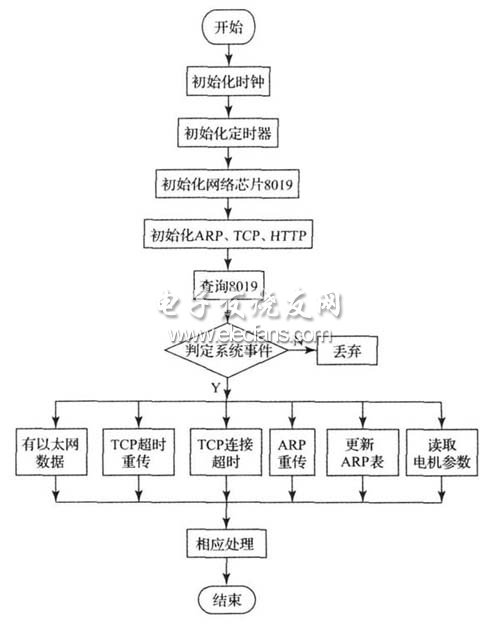
Figure 3 System software flow
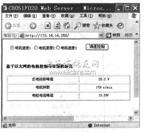
Figure 4 System WEBSERVER interface
5 Conclusion
The system realizes the transplantation of TCP / IP protocol based on 8-bit microcontroller, and realizes the web page data transmission function and motor parameter query and motor control. The application here is just an example, and because the price of embedded Ethernet is low, I believe that in the near future will be more widely used in the industrial field.
Headphone speaker is a king of speaker unit which is used for headphone, it also called headphone driver. These speakers have high sound pressure level, fast frequency response, wide frequency response range and low distortion. Headphone Speakers are mainly used for voice headphone (e.g. customer service phone, call center headphone, military intercom headset- ) and music headphone (e.g. Bluetooth headphone, sport headphone, game headphone-).
Our main headphone speakers include:
1) From the diameter, we have speakers in 23mm ~ 57mm.
2) From the impedance, we have speakers of 32ohm/150ohm/300ohm/1000ohm.


FAQ
Q1. What is the MOQ?
XDEC: 2000pcs for one model.
Q2. What is the delivery lead time?
XDEC: 15 days for normal orders, 10 days for urgent orders.
Q3. What are the payment methods?
XDEC: T/T, PayPal, Western Union, Money Gram.
Q4. Can you offer samples for testing?
XDEC: Yes, we offer free samples.
Q5. How soon can you send samples?
XDEC: We can send samples in 3-5 days.
Bluetooth Headphone Speaker,Sport Headphone Speaker,Hifi Headphone Speaker,Music Headphone Speaker
Shenzhen Xuanda Electronics Co., Ltd. , https://www.xdecspeaker.com