When engineers debug various boards, they often have a boot error and the system cannot be opened normally. Next, we will list some common system problems that may be caused when the board is powered on, and explain the correct initialization of the board. The basic principle.

Many ICs contain POR circuits
(Power-on reset, ie Power-on Reset)
(Power-on reset, ie Power-on Reset)
(Power-on reset, ie Power-on Reset)! The important thing is said three times!
Its role is to ensure that the analog and digital modules are initialized to a known state after the board is powered up.
POR three steps: the power supply voltage reaches the threshold voltage - the POR circuit will release the internal reset signal - the state machine begins to initialize the device.
The device ignores external signals, including transmitted data, before initialization is complete. The only exception is the reset pin, which uses the internal strobe of the POR signal.
1.1 What does the POR circuit look like?
First popular science concept, window comparator: commonly used two comparators (double comparator), it has two threshold voltages VT2 (high threshold voltage) and VT1 (low threshold voltage), if VT1 ≤ VA ≤ VT2, Vout outputs a high level; if VA<VT1, VA>VT2, Vout outputs a low level.
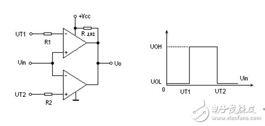
Figure 1 Dual comparator
The POR circuit can be represented as a window comparator, that is, once the operating voltage falls between the high and low thresholds, the circuit is automatically reset. As shown in Figure 1.1.
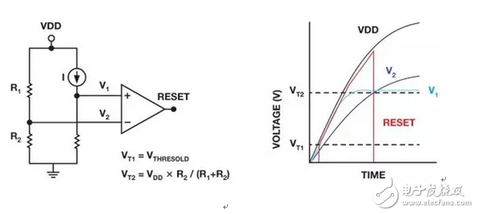
Figure 2 simplified POR circuit
1.2 How does POR work?
The comparator window is usually defined by the digital power level. The digital module controls the analog module, and the voltage required for the full operation of the digital module is similar to the minimum voltage required for the analog module to operate.
A higher VT2 threshold is better for analog modules. If the recommended minimum supply voltage is too close, the reset may be accidentally triggered when the voltage is slightly reduced.
If the device includes separate analog and digital supplies, one strategy to avoid failure is to add a POR circuit that holds both modules in reset until the supply voltage is high enough to ensure proper operation of the circuit.
1.3 How does POR deal with short-term power outages?
The POR circuit sometimes incorporates a Brownout Detector (BOD) to prevent the circuit from resetting when the voltage drops unexpectedly for very short periods of time. In fact, the power-down circuit adds hysteresis to the threshold voltage defined by the POR module, typically around 300mV. BOD guarantees that POR will not generate a reset pulse when the supply voltage drops below VT2 unless the supply voltage drops below another threshold VBOD (VT2-300mv), as shown in Figure 1.2.
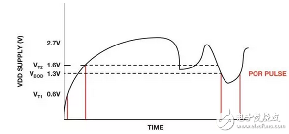
Figure 3 Power failure detection
The power-down threshold level is sufficient to ensure that the digital circuitry retains information, but not enough to ensure proper operation. Thus, if the power supply level is only reduced very briefly, the controller can suspend activity when the power supply drops below a certain level, leaving the entire device free from reinitialization.
1.4 Three situations to be mastered when power is turned on correctly
1. Monotonic power supply has a shock
The actual POR circuit is much more complicated than the simplified version shown in Figure 1.1. The POR circuit requires a startup module to generate the start pulse. In this case, a monotonic power supply (monotonically rising or falling without a oscillating power supply) must be used because If a non-monotonic power supply is used, non-monotonic slopes can cause problems when the deviation approaches any threshold level.
A higher threshold deviation causes the same non-monotonic sequence to be valid for one component and not for other components, as shown in Figure 1.3.
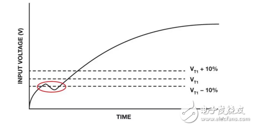
Figure 4 Non-monotonic power ramp 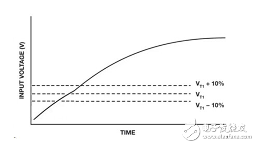
Figure 5 Monotonic power ramp
Solution: Use a monotonic power supply to avoid problems caused by the slope.
Second, the system can not start? May be residual pressure
In some cases, even if the power is turned off (disabled LDO), the storage capacitor will retain a certain residual voltage, POR will not reset properly, and the device will not initialize properly. As shown in Figure 1.4.
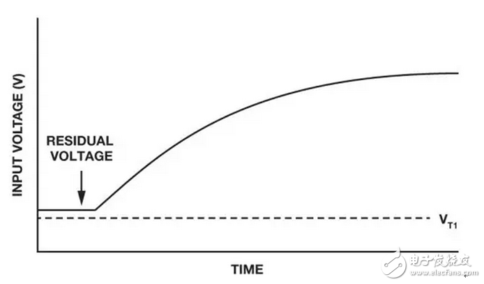
Figure 6 residual pressure
Solution: This voltage should be as small as possible to ensure that the residual voltage can drop below VT1.
Third, how to arrange the power-up sequence?
Some data sheets give the recommended power supply "timing" that should be applied to devices with more than one power supply pin. It is important to follow this sequence. For example, consider a device with two independent power supplies.
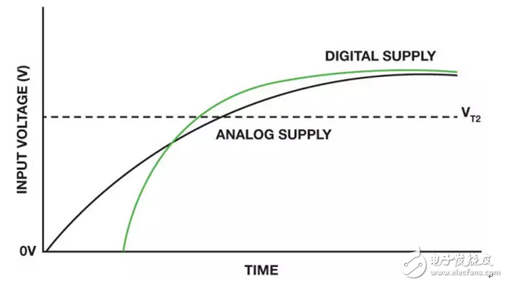
Figure 7 recommended power-up sequence
Solution: The recommended power supply sequence requires that the digital power supply be powered prior to the analog power supply (this is conventional because the digital module controls the analog module, so the digital module must first be powered) and the module must be initialized first. It doesn't matter which power supply starts to rise first, but the digital power supply must cross the threshold before the analog power supply, as shown in Figure 1.5. If the delay between power supplies is around 100 μs, the effect should be small and the device should be properly initialized.
Fourth, other summary
A slow power ramp of hundreds of ms can cause problems due to internal triode parasitics. The POR circuit is evaluated at various slew rates to ensure proper operation under normal power conditions. The data sheet will indicate if a fast power ramp (100 μs or less) is required.
For example, for a board that is connected to a power supply with a thin cable, a poor ground connection can have high impedance, which can cause spurs during power-up. In addition, in some electromagnetic environments (EME), the parasitic gate capacitance of a MOS transistor may be charged, causing the transistor to not function properly unless the capacitor is discharged. This may cause POR initialization to fail.
Drift and tolerance also need to be considered. In some cases, discrete components such as capacitors have high tolerances (up to 40%) and high drift (drift with temperature, voltage, and time). In addition, the threshold voltage has a negative temperature coefficient. For example, VT1 is 0.8V at room temperature, 0.9V at -40°C, and 0.7V at +105°C.
What is Full spectrum led chip ?
It is the newest trend for indoor plants.Advanced Led Grow Lights chip,not provide sigle color ,provide broad spectrum 400nm~840nm , simialr with sun light ,but most is red and blue ,it is best for plant grow.This is a revolutionary step for LED Vegetation Lights which have previously been unable to act as the sole light source for the indoor garden. Suitable for all stages of plant growth.
Advantages
Plug with listed certificate safe to use.


Item Display


Ageing Test

Application
Ideal for all phases of plant growth, and works well with water solution culture and soil culture. Can be used in house garden, pot culture, sowing, breeding farm, flower exhibition, bonsai garden, green house, sowing farm, greenhouse cultivation, water soluble breeding, pipeline cultivation and so on.

Our Quality Control systems and after-sales

Package


Warnings:
1.lndoor use only.
2.To avoid being damaged,do not use water or drip irrigation while using.
3.Sunshine lighting time should be 12-18 hours.
4.While irradiating the plants,the height of led grow lamp is not less than 10 inches,
low height will cause the destruction of plants.
5.Highly hang the lamp will weaken the energy and affect the growth cycle of the
plants, so the lamp should not be hung too high.
6.While taking care of the plants, please spray the leaves and branches 2-3 times everyday,
to ensure the the plants do not wrinkle a wither, and have no phenomenon of few fruit, and
hard pericarp.
Trade Terms
Payment: T/T, L/C, Paypal, 30% deposits before production, 70% balance to be paid before deliverying(Western Union are welcome)
Sample will be delivered within 7 working days.
Discounts are offered based on order quanlityes.
MOQ:sample order are acceptable
Delivery ways:DHL,UPS,FedEx,TNT, door to door,by sea,by air,etc.
Philion is a company that makes it possible to produce fresh vegetables:
Where it is too hot or too cold,
Where there is too much or too little sunlight,
We create in a complete closed indoor environment the optimal conditions to grow.
Led Grow Lights For Vegetables
Led Grow Lights For Vegetables,Led Vegetable Light,Led Vegetables Grow Lights,Energy Saving Led Grow Lights
Shenzhen Phlizon Technology Co.,Ltd. , https://www.philizon.com