Overview: Electromagnetic interference is a problem that cannot be ignored in electronic products. Measures should be taken during design. Good design will reduce design time and product cost. Starting from the requirements of the national standardization organization for electromagnetic interference, the three main reasons for the electromagnetic interference generated by the digital video disc player are analyzed. The targeted discussion from the three aspects of switching power supply, audio/video output and PCB circuit board, design analysis Several methods to suppress electromagnetic interference have passed the EMI test.
Electromagnetic Interference (EMI) refers to an electronic device that continuously discharges interference into the environment in which it is located beyond the allowable range. In order to protect the environment, the National Standards Organization has established a number of mandatory standards, requiring electronic equipment manufacturers to reduce the electromagnetic interference of their products to a certain extent. Therefore, from the beginning of design, we must pay attention to the EMI design of electronic equipment, from the selection of components, connectors, layout and wiring of printed boards, grounding points and other aspects to reduce electromagnetic interference. This article takes the DVD-1000 digital video disk machine as an example to introduce the experience of EMI design.
This article refers to the address: http://
1 EMI design requirements For the EMI requirements of electronic products, China issued the “GB13837-1997 Standards for Limits and Measurement Methods for Radio Interference Characteristics of Sound and Television Broadcast Receivers and Related Equipment†in July 1997, which specifies Five limits for electromagnetic interference.
(1) The disturbance voltage injected into the power supply. In the range of 9 to 30 kHz, if the interference voltage of the electronic equipment injected into the grid exceeds 66 dBμV, the interference signal will cause serious interference to other equipment through the power network, which may cause other equipment to degrade or fail to work properly.
(2) Antenna end disturbance voltage. When the receiving device is connected to a common antenna or the antennas are very close together, the interference signals are easily interfered by the distribution cable or the coupling between the antennas.
(3) RF output useful signal and disturbance signal levels. When the RF output of the device is connected to other devices, if the RF output of the device and its harmonic level are too high, the generated high-frequency harmonic radiation will cause interference to nearby devices.
(4) Radiation disturbance field strength or power. The local oscillator of the broadcast receiver and its harmonics, the radiation field strength of an intermediate frequency unit should not be too high, otherwise it will pollute the electromagnetic environment.
(5) Harassment power. Devices such as audio power amplifiers and audio-visual discs radiate energy at frequencies above 30 MHz mainly through their connected power lines and other connections. When the peak of the disturbance power on the power line and other wires is greater than 55 dBμV, it will affect the normal operation of other devices.
2 EMI propagation mechanism of digital video player EMI transmission is mainly divided into conductive interference and radiation interference. Radiated interference refers to the interference between various systems. It radiates various electromagnetic interference generated inside the electronic product to the external electromagnetic field through the lead wires and components in the form of space electromagnetic waves, thereby causing interference to other electronic devices. For example, the high-frequency signal lines of DVD player and various connectors may become sources of radiation interference with antenna characteristics. Conducted interference is the interference formed by the signal coupling between the internal conduction of the system through the conductive medium. It is usually due to the intersection of the impedance (internal resistance of the power supply, the impedance between the ground lines) and the mutual inductance (guide line). Internal interference caused by the intersection of parasitic capacitance. For example: the radiation of a television set.
There are many specific methods for eliminating or reducing electromagnetic interference, including shielding technology, power supply filtering, grounding technology, and the use of EMI devices. For DVD digital video disc players, because there is no antenna and RF output port, the antenna end disturbance voltage is very small, mostly less than 30 dBμV. The main propagation paths are as follows: the pulse current and voltage generated by the switching power supply change rapidly, forming The switching power supply switching pulse and higher harmonics radiate and conduct outward through the components and the power line to generate electromagnetic interference; the audio/video output signal radiates outward through the audio/video signal connection line; various clocks required for digital circuit operation The signal and its higher harmonics, such as the CPU chip operating clock, MPEG decoder operating clock, video synchronization clock (27 MHz, 16.934 4 MHz, 40.5 MHz), form an interference pulse that radiates outward through the component.
3 EMI design
3.1 EMI Design of Switching Power Supply Switching power supply is an important part of electronic equipment. Electrical signals operating in electronic devices are much smaller in magnitude and energy than switching power supplies, which means that switching power supplies are often the strongest source of interference for electronic devices. There are many reasons for the interference generated by the switching power supply. For example, the input current of the switching power supply contains more noise due to the random variation of the load and voltage in the external power grid. The high-speed switching between the internal power switch tube between the cut-off and the conduction is rich. Subharmonic interference, abrupt spike current interference generated by reverse recovery of the rectifier diode, high-rate varying voltage and conducted interference caused by distributed capacitance to ground. In the DVD digital video disc player, in order to reduce the EMl interference of the switching power supply, the following measures are taken:
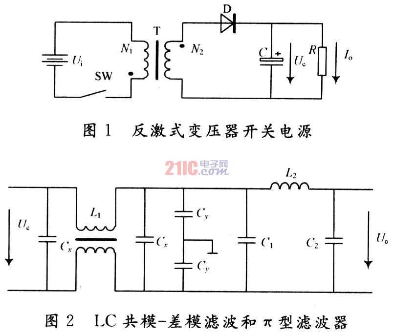
3.1.1 EMI Design of Switching Transformer To reduce the interference in the power supply circuit, firstly, the switching transformer adopts the flyback excitation mode. The schematic diagram of the flyback transformer switching power supply is shown in Figure 1. Ui is the input voltage of the switching power supply, T is the high frequency transformer, and SW is the control switch. Due to the presence of the rectifier diode, the flyback switching power supply does not provide power output to the load during the control switch is turned on, and the stored energy is converted into the back electromotive force to the load output only during the control switch off period. Therefore, when the input power source changes The switching power supply can not immediately reflect the output voltage and current, and only works when the power is turned off in the next working cycle, that is, the transient response of the output voltage of the flyback switching power supply is slow; and at the same time, due to the energy storage filter capacitor The large capacity makes the output voltage stable and reduces high frequency interference.
In addition, the flyback power transformer should pay attention to the size of the transformer air gap. The larger the air gap is, the stronger the load capacity of the transformer is. However, the leakage inductance of the transformer is larger. Under the premise of satisfying the load capacity, the leakage inductance should be as small as possible. To reduce the interference caused by leakage inductance. At the same time, in order to reduce the stray capacitance of the primary and secondary sides. A copper layer shielding layer is added between the primary and secondary of the transformer to cut off the primary and secondary interference propagation channels.
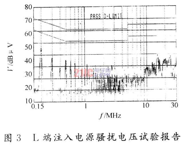
3.1.2 Switching transformer output filter design Good filtering technology has obvious effect on EMl of switching power supply. The LC common mode-differential mode filter and π-type filter (shown in Figure 2) are connected to the output of the switching transformer to suppress EMI interference in the switching power supply. Cx is the power supply cross-connect capacitor, filtering out the common mode interference signal, commonly used ceramic capacitor or polyester film capacitor, taking 0.22 ~ 0.47μF; Cy is the bypass capacitor, filtering out the differential mode signal, below 4 700 pF, The excessive capacitance affects the insulation performance of the equipment; L1 is a common mode coil composed of two windings wound on the same high permeability core, and the inductance is several tens of mH. Adjust the inductance and capacitance so that the resonant frequency is close to or close to the center frequency of the interference frequency. For high frequency electromagnetic interference, you can use a three-terminal capacitor or a feedthrough capacitor for filtering.
In addition, the leads and connecting leads of Cx and Cy should be as short as possible so that the grounding impedance is as small as possible, and the noise can be bypassed to the ground through the capacitor; the filter is as close as possible to the input port. Avoid coupling the filter input and output, and lose the filtering effect.
3.l.3 MOS type switch integrated circuit adopts STR6651 MOS type switch integrated circuit, which is a semiconductor device with majority carrier motion. The required driving power is small, the electromagnetic radiation energy of the components of the driving circuit is small. . In addition, the switch integrated circuit includes a pulse spike absorbing circuit, so that the peak interference is greatly reduced.
3.2 Audio/Video EMI Design
3.2.1 Using Cables with Filtered Connectors In audio/video design, the weakest EMI design is the cable that connects the devices. Ordinary shielded cable is a metal-made mesh. The holes above will leak at high frequencies and cannot meet the shielding for high-frequency interference. For this purpose, a cable with a filter connector is used, and a low-pass filter is placed over the hole of each connector to eliminate high-frequency interference on the signal line. Thereby reducing the radiation above the cable.
3.2.2 EMI Devices Connected in Series with Audio/Video Outputs Different EMI devices have different high frequency attenuation frequencies, and their parameter selection should be determined according to EMI test. For example, in a DVD-1000 digital video disc player, the parameters of audio EMI are: at 100 MHz, Z = (1 000 ± 250) Ω. Thus, the high frequency energy of the output signal is greatly reduced, that is, the high frequency interference is greatly reduced.
3.2.3 Audio/Video Output Wiring To reduce the grounding resistance and eliminate the influence of distributed capacitance, the audio/video output RCA is grounded with a large area, and its grounding end is connected to the metal casing. At the same time, the video D/A and audio are enhanced. The D/A is designed so that the high frequency harmonic components in the output signal are small. 3.3 EMI design of PCB board Pay attention to EMI design in the layout of the device. Each functional circuit is centered on the core chip, and related components are arranged around the core chip; the signal of each functional circuit is smooth, and the phenomenon of signal reflow is minimized; Keep away from I/O ports and connecting lines such as keypads and remote control receiver boards; each signal connection line cannot cross the circuit with large interference; arrange the reset circuit and clock circuit as close as possible to the device pins; arrange the position of the filter capacitor reasonably. The filter capacitor should be as close as possible to the device pins that need to be filtered.
In PCB layout, analog and digital circuits must be routed within their functional areas, prioritizing important devices and important signals (clock/address/data/reset lines, etc.) to ensure these connections are the shortest; metal for crystal oscillators The outer casing should be well grounded. The signal line should not be taken under the crystal oscillator. The EMI device for the connection terminal and I/O port must be placed at the connection terminal and I/O port, and the signal trace must pass through the EMI device. To the terminal, etc.
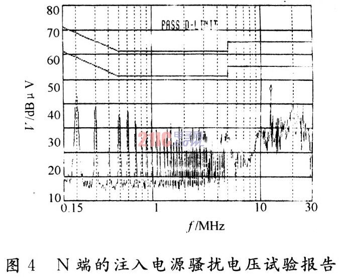
3.4 EMI Test Results of DVD Digital Video Disc Player After the above EMI design and measures, the DVD-1000 digital video disc player effectively reduced high frequency interference and passed the domestic EMI test. image 3. Figure 4 shows the test report of the injected power disturbance voltage at the L and N terminals.
4 Conclusion DVD digital video disc players have many potential sources of radiation, which can interfere with the environment, so that the design can not pass the 3C argument. As a designer, the conscious awareness of EMI should be implemented as early as possible to eliminate electromagnetic interference and fundamentally improve the quality and reliability of products.
|
Nominal Diameter (mm) |
Diameter Tolerance (mm) | Tensile strenght (Mpa) | Yield strenght (Mpa) | Elong.at max.force | Bending number 180o |
| 4 | ±0.04 | 1470 | 1290 | 3.50% | 4 |
| 4.8 | 1570 | 1380 | |||
| 5.00 | ±0.05 | 1670 | 1470 | ||
| 1770 | 1560 | ||||
| 1860 | 1640 | ||||
| 6.00 | 1470 | 1470 | |||
| 6.25 | 1570 | 1570 | |||
| 7.00 | 1670 | 1670 | |||
| 7.50 | 1770 | 1770 | |||
| 1860 | 1860 | ||||
| 8.00 | ±0.06 | ||||
| 9.00 | 1470 | 1470 | |||
| 9.50 | 1570 | 1570 | |||
| 10.00 | 1670 | 1670 | |||
| 11.00 | 1470 | 1290 | |||
| 12.00 | 1570 | 1380 |
Steel Wire Armoured Cable, commonly abbreviated as SWA is also called booklet armored cable, mains or power cable, is a hard-wearing power cable designed for the supply of mains electricity. It is one of a number of armoured electrical cables – which include 11 kV Cable and 33 kV Cable – and is found in underground systems, power networks and cable ducting.
Gavanized Steel Wire,Steel Wire Armoured Cable
Huayuan Gaoke Cable Co.,Ltd. , https://www.bjhygkcable.com