0 Preface
In recent years, LED display technology has developed rapidly, and CRT has become a mainstream display technology in many fields. Accordingly, backlight technology, which is one of the core technologies of LED display, has also been greatly developed [1, 2]. In 2004, SONY launched the world's first 117cm (46 in) LCD TV (QUALIA 005) with LED as its backlight. Its high-definition image gives people a new color experience [3]. Followed by AUO, Samsung, LG, Phillips and other companies have also launched their own large-size LCD TVs with LED backlights [4], large-size LED backlights have become a hot spot for research and development. At present, LED backlight modules mainly use side-light and direct-type [5].
1 LED backlight technology
1.1 Regional Control Technology
With the advent of high-power LEDs and increased efficiency, the power consumption of direct-lit type is decreasing. The direct-lit LED backlight also has a breakthrough technology—local dimming, also known as dynamic backlighting, which greatly reduces the power consumption of the backlight and improves the contrast of TV products. However, the number of LEDs is required to be relatively large, so the thickness of the TV product is relatively large, and the aesthetics and flexibility are slightly poor.
The area control technology determines the brightness or color of the backlight according to the image content of the area to be displayed, and modulates the LED control signal to effectively save power consumption and improve contrast while maintaining image brightness. In the most bright place, when the liquid crystal cell in the cell is completely turned on, the maximum Voltage is applied to the corresponding LED cell to maximize the brightness; and the darkest place is the liquid crystal cell in the cell. It is completely turned off, and the voltage of the corresponding LED cell is also reduced to the minimum (or off), thus reducing light leakage. FIG. 3 is a comparison diagram of a conventional liquid crystal display algorithm for a backlight and an area controlled backlight. Figure 1 (a) shows the flow of the conventional liquid crystal display algorithm using the uniform backlight illumination method; Figure 1 (b) shows the flow of the backlight liquid crystal display algorithm using the area control, and the backlight drive signal determined by the input image content is non-uniform. The dynamic backlight, and based on the known backlight light diffusion distribution, the LED signal is determined by the input image and the liquid crystal compensation signal. The actual area control technology adopts different methods according to the acquisition of backlight driving signals, the distribution of backlight intensity and the compensation of liquid crystal screen signals [6].
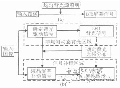
Fig. 1 Comparison of algorithm flow of traditional backlight and area control backlight (a) Flow of traditional backlight liquid crystal display algorithm;
(b) The process of regionally controlling the backlight liquid crystal display algorithm.
1.2 direct down technology
At this stage, large-size direct-lit LED backlights are developing toward large-size side-entry LED backlights, following the current requirements of low-carbon, green, environmentally-friendly, ultra-thin, high-color displays, and the side-entry LED backlights in the later stages. The area control backlight does not reach the optimal value, we need to be thinner in the direct-type backlight technology, through the micro-structure processing of LGP, and printing on the light guide plate, so that the LED light can reach the light-mixing at the shortest distance. It is required to improve the transmission efficiency of the light source in the LGP and change the light loss caused by the long-distance transmission of the original side-entry type. At the same time as the large-size direct-type backlight is ultra-thin, the local dimming technology is completed to achieve low power consumption, and RGB LED or high-power white LED (RGB phosphor) is used on the basis of direct-type technology to achieve ultra-thin, Low-power, high-color backlight products [15].
The main goal of the direct-lit LED backlight design is to allow the light emitted by the LEDs mounted on the bottom PCB to pass through the diffusing film and the brightness enhancing film to form a uniform brightness distribution. Its structure is shown in Figure 2:
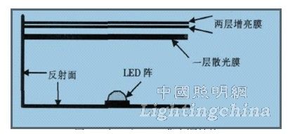
Figure 2 Direct-lit LED backlight structure
The thickness of the direct-lit backlight is determined by the distance between the bottom of the light box and the diffuser plate. Generally, the thicker the thickness, the better the light uniformity of the backlight. In the case of a thin backlight, color and brightness uniformity become the key to the direct backlight. The type of light field distribution of the LED lamp plays an important role in the color and brightness uniformity of the backlight. Currently, the LED lamp used in the backlight usually has two types of Lambertian and edge emission types, and the edge emitting type LED is more advantageous for the backlight. For light uniformity, direct-lit backlights mostly use edge-emitting LEDs. However, the LED emitted at a large angle is likely to cause dark spots due to the low light intensity in the middle, which affects the uniformity of the backlight. Through theoretical analysis and simulation, we find a kind of LED light whose light field distribution is more suitable for backlight uniformity. Since the LED light-emitting area is small, it can be approximated as a point source, with its light intensity I = I (θ) and the diffuser plate at the top of the LED, as shown in the figure [7]:

Figure 3 LED light path diagram
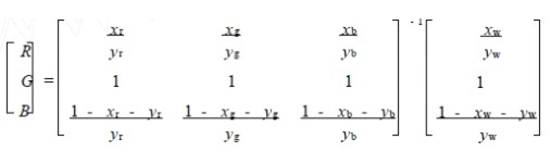
Brightness is defined as the luminous flux per unit area and unit solid angle. When the viewing angle of the LCD is fixed, the brightness uniformity is equivalent to the uniformity of the illuminance distribution on the astigmatism film. The general LED light field distribution is a Lambertian distribution of approximate cosine, and it is difficult to form a uniform illuminance distribution on the astigmatism film. Therefore, this paper proposes a secondary optical design for the LED light source, so that it can form a uniform illuminance distribution on the astigmatism film, and finally form a uniform emission through the scattering mechanism of the astigmatism film. The LED backlight combines the three primary colors of red, green and blue to generate white light while achieving uniform brightness distribution. When the wavelengths of light emitted by the three primary color LEDs of red, green, and blue are known, the ratio of the luminous flux of the respective wavelengths of light required to generate white light is calculated by the following equation.
 (1)
(1)
In the formula, (Xr, Yr), (Xg, Yg), (Xb, Yb) are the red, green, and blue color coordinates, and R, G, and B are the luminous flux ratios of red, green, and blue, respectively. If the brightness uniformity of the monochromatic light can be ensured, the color uniformity of the white light after the color mixing can be guaranteed [8].
2 LED backlight in the field of LCD TV applications
Liquid crystal, referred to as LCD (Liquid Crystal Display, LCD mainly uses liquid crystal display panel, the main components include: fluorescent tube, light guide plate, polarizing plate, filter plate, glass substrate, alignment film, liquid crystal material, thin film transistor, etc. [9].
The working principle of the liquid crystal display panel is that two thin glass plates are pressed and evacuated and sealed with an inert gas (pressure 2.674×10⁴ Pa), and a thin space is added on the surface of the rear glass substrate and the front glass substrate (thickness). 0.2mm), a small hole is reserved to inject water and lead the wire. Thus, a water film is formed on each of the front glass substrate and the rear glass substrate, which is equivalent to two large-area electrodes, and then, depending on the conductivity of water, after the voltage is applied thereto, the entire surface uniformly and stably emits white fluorescence.
Firstly, the liquid crystal display must use the backlight, that is, the light is spontaneously radiated by the fluorescent tube LED, and the light passes through a polarizing plate and then through the liquid crystal, and the arrangement of the liquid crystal molecules at this time changes the angle of the light penetrating the liquid crystal. The light must then pass through the front color filter and another polarizer. Therefore, as long as the voltage value of the stimulating liquid crystal is changed, the intensity and color of the final light can be controlled, and in turn, a combination of different shades of color can be displayed on the liquid crystal panel. The image can be understood as: the screen of the liquid crystal display is based on countless small light bulbs (LED fluorescent tubes to display images, but each small light bulb is only a few millimeters or even micrometers. After a few square meters, the corresponding light bulb is lit. You can see the words or graphics you want. So when you buy an LCD TV or monitor, you need to see if there is any sand point, that is, if there is any small light bulb that doesn't work: turn the monitor all black or white to see if there are any other colors. The small point, because the black and white contrast is very clear, can be directly seen with the naked eye [10].