In high-speed serial communication, clock information is typically embedded within the data stream through encoding techniques. At the receiving end, a clock recovery circuit extracts this embedded clock and uses it to properly sample the incoming data. This process is essential for reliable data transmission, as accurate timing is crucial for correctly interpreting the received signal. The core of this process is the Clock Data Recovery (CDR) circuit, which ensures that the recovered clock aligns with the transmitted data, even in the presence of jitter and frequency drift.
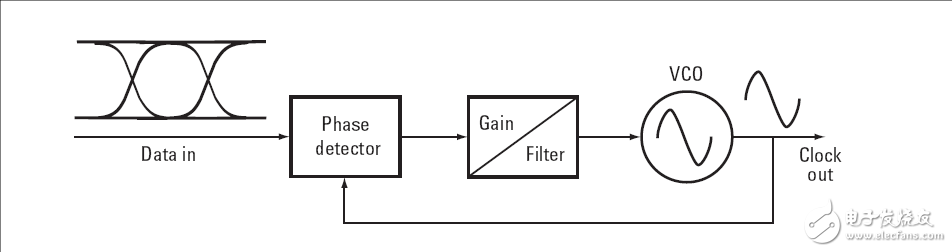
The CDR circuit usually employs a Phase-Locked Loop (PLL) to achieve synchronization. The PLL compares the input data signal with the output of a Voltage-Controlled Oscillator (VCO). Any frequency or phase difference between the two generates an error signal, which is then filtered and used to adjust the VCO's output frequency. This feedback mechanism allows the system to lock onto the correct clock frequency, ensuring stable and accurate data sampling. The loop filter plays a key role in smoothing out rapid phase changes, allowing only low-frequency variations to affect the VCO output.
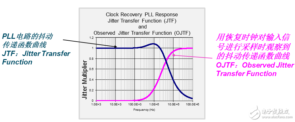
The performance of the PLL is often evaluated using the Jitter Transfer Function (JTF), which describes how well the circuit can track different frequency components of jitter. Typically, the JTF behaves like a low-pass filter, meaning it effectively tracks low-frequency jitter but suppresses high-frequency jitter. This has important implications for signal integrity, as low-frequency jitter may be visible in the recovered clock, while high-frequency jitter is filtered out.
When a receiver samples data using the recovered clock, any low-frequency jitter in the signal is also reflected in the clock, resulting in minimal impact on setup and hold times. However, high-frequency jitter is not tracked by the CDR, leading to increased jitter in the sampled signal. This relationship is often represented by the Observed Jitter Transfer Function (OJTF), which shows how jitter appears from the receiver’s perspective.
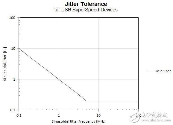
Many high-speed serial bus standards, such as USB 3.0, define specific tolerances for different types of jitter. These specifications show that receivers are more tolerant of low-frequency jitter than high-frequency jitter. For example, USB 3.0 can tolerate up to one UI (unit interval) of low-frequency jitter, highlighting the importance of proper clock recovery in maintaining signal integrity.
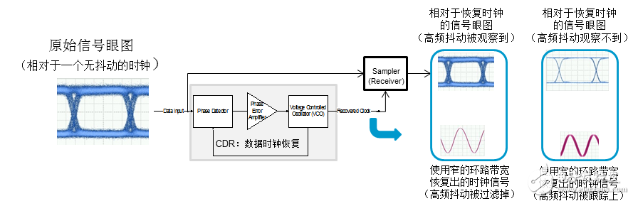
The bandwidth of the PLL loop significantly affects the performance of the CDR. A narrower loop bandwidth results in a cleaner recovered clock but limits the ability to track jitter. Conversely, a wider loop bandwidth improves jitter tracking but may allow more noise into the clock. This trade-off directly impacts the quality of the eye diagram and the overall signal integrity. The figure below illustrates how different PLL bandwidth settings influence the recovered clock and the resulting eye pattern.
When testing high-speed serial signals, it is critical to simulate the clock recovery behavior of the actual receiver chip. This ensures that the test conditions match real-world scenarios, avoiding misleading results. Different buses have their own requirements for loop bandwidth and filter characteristics. For instance, optical communication systems often use a loop bandwidth of 1/1667 or 1/2500 of the data rate, while PCIe, USB 3.0, and SATA have their own defined specifications.
To support these diverse requirements, test instruments must offer flexible clock recovery options. Modern oscilloscopes often use software-based CDR solutions, allowing users to adjust loop bandwidth settings easily. In contrast, some hardware-based systems, such as sampling oscilloscopes or BER testers, rely on dedicated clock recovery circuits that must be configured to meet specific test standards.
In summary, clock recovery is a fundamental aspect of high-speed serial communication. Properly designed CDR circuits ensure reliable data sampling, reduce jitter, and maintain signal integrity. Understanding the relationship between loop bandwidth, jitter, and eye diagrams is essential for both design and testing. By matching the clock recovery behavior of the receiver, engineers can ensure accurate and meaningful test results.
This Automation curtain is specially designed for automation industry. SDKELI LSC2 light curtain is designed for automation field, with small size, compact structure and strong anti-interference ability, and the product meets IEC 61496-2 standards. The automatic light curtain is with reliable quality and very competitive price. It has been used in many factories and has replaced curtains from Omron, Banner, Keyence, etc.
Automatic Light Curtain,Laser Light Curtain,Automation Light Beam Sensor,Automatic Infrared Beam Sensor,Infrared Beam Curttain Sensor,Infrared Beam Sensor
Jining Keli Photoelectronic Industrial Co.,Ltd , https://www.sdkelien.com