1 Composition of JP7-T GPSOEM board
This design compares and weighs several kinds of GPS data investigated according to the actual project needs, and finally selects the JP7-T (SIRF2) GPS module produced by FALCOM of Germany. The module has 12 channels GPS receiving module, complete temperature compensated crystal oscillator, SiRF2 type chip-low power chip set, advanced TIFF frequency, 3 different power supply modes, smaller size, PIN pin is compatible with With memory function, Falcom memory query software is embedded at the same time. Using this module as the core part, the author also designed a demo board for testing. The process of the internal signal flow of the JP7-T (SIRF2) GPS module produced by FAL-COM is shown in Figure 1.

JP7-TX series GPS positioning system uses L1 signal frequency (1575.42MHz). The module can be divided into four major blocks: RF signal down converter, digital baseband demodulation, embedded ARM microprocessor and 8MBitFlash memory for storing built-in GPS software. The first two are used for hardware circuit processing, and the ARM microprocessor can use the built-in GPS software to calculate the GPS position, speed, time, etc.
The radio frequency part of the system is used for compensation and filtering of GPS signals (usually a 130 dBm), and then it is converted into an intermediate frequency signal and output to the signal processing part. The function of the digital baseband demodulator is to carry the quantized GPS signal and the serial bit stream data and accompanying pseudo-sequence of the detection satellite. This process obtains serial data by spreading the spectrum and shifting the Doppler frequency portion of the signal. The ARM microprocessor is used to supervise the channel allocation and extract the original satellite tracking data. At the same time, after calculating the position and time, it is sent to the high-level application part in a serial manner. Hardware circuits that support microprocessor processing include RTC and reset pulse generator circuits. The built-in GPS software is used to manage the channel allocation, and can use the pseudo-sequence of the satellite to calculate the position, speed and time, and reformat the data format to output to the serial port or used for local decision-making.
2 Demo board design of JP7-TGPS receiver
After understanding the internal principles of the JP7-TGPS module, it is necessary to know whether it is suitable for the design needs of the product, and then design a demo board to perform performance testing. The basic hardware design block diagram of the Demo board is shown in Figure 2.
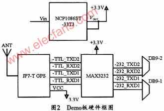
By analyzing the internal circuit and pins of the GPS module, it can be seen that the 4 and 5 pins are the first group of I / O ports, respectively SDI1 and SDO1, of which SDI1 is the main receiving channel. Used to receive software commands from the GPS board, SDO1 is the main transmission channel used to transmit navigation data to the user program; Pins 6 and 7 are the second group of I / O ports, respectively SDI2 and SDO2; The pin is RF_IN, used to provide GPS with the signal received from the antenna; Pin 19 is used to provide power for the antenna. Among them, SDI and SDO are TTL level, so before connecting it to the PC through the RS-232 serial port for testing, you must convert the TTL standard signal to a 232 standard signal to communicate with the PC. This design uses MAX3232 Flat conversion chip, its conversion circuit is shown in Figure 3. In view of the frequency of the GPS module and the design needs of the project product, this design selects a 5-meter GPS magnetic chuck antenna for vehicles, whose center frequency is also L1, and its positioning accuracy for receiving satellite positioning information is less than 15 meters.

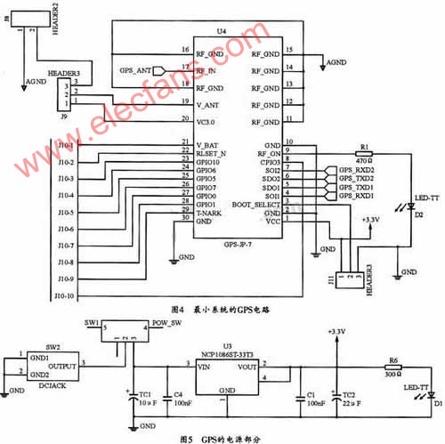
Figure 4 shows a GPS receiver circuit designed based on the minimum startup circuit of JP7-T. Figure 5 shows the circuit diagram of the power part of the circuit.
3 software design
The software part of this system mainly completes the collection, decoding and display of latitude and longitude, UTC time, GPS positioning effectiveness, mobile terminal speed. This design converts the latitude and longitude of WGS-84 coordinates to degrees, UTC time to Beijing time, and the knop unit of speed to km / h.
3.1 GPS data format of JP7-T
The NMEA-0183 protocol is a GPS interface protocol standard developed by the National Marine Electronics Association (NaTIonaI Marine Electronlcs AssociaTIon). The NMEA-0183 protocol defines several statements that represent different meanings, and each statement is actually an ASCII code string. This code is relatively intuitive and easy to identify and apply. The data sent to the computer is mainly composed of frame header, frame tail and intra-frame data. The frame header is different according to the data frame. The frame header mainly includes "$ GPGGA", "$ GPGSA", "$ GPGSV" and "$ GPRMC". These frame headers identify the structure of the data in the subsequent frames. Each frame uses the carriage return and line feed characters as the end of the frame to identify the end of a frame. You do not need to know all the information of the NMEA-0183 communication protocol during use, you only need to select the part of the positioning data you need from it, and ignore the rest of the information.
The GPS navigation data used in this project can be obtained in the "$ GPRMC" frame. The frame format is as follows:
The fields in the format are explained as follows:
(1) Greenwich Mean Time at the current position, the format is hh-mmss;
(2) Status, A is a valid position, V is a non-effective receiving warning, that is, the number of satellites above the current antenna field of view is less than 3;
(3) Latitude, the format is ddmm.mmmm;
(4) Used to mark the northern and southern hemispheres, N is the northern hemisphere and S is the southern hemisphere;
(5) Diameter, the format is dddmm.mmmm;
(6) Used to mark the eastern and western hemispheres, E is the eastern hemisphere, W is the western hemisphere;
(7) The speed on the ground, the range is 0.0 to 999.9;
(8) Azimuth, the range is 000.0 to 359.9 degrees;
(9) Date, the format is ddmmyy;
(10) Geomagnetic change, from 000.0 to 180.0 degrees;
(11) Geomagnetic change direction, E or W
3.2 Design process of positioning information system
The JP7-T manual indicates that the baud rate of the GPS NMEA to be used is 4800, so the serial port baud rate can be set to a fixed value of 4800 in the software.
(1) Time conversion
The time received by GPS is UTC time, so it should be converted to Beijing time. The core algorithm is: hour + 8; year + 2000; at design time, if hour is greater than 24, then dav + 1, hour-24; then according to the month and whether it is a leap year to determine whether there are corresponding months to be processed after day processing; According to the processed month, judge whether the year should be processed successively, etc. It should be noted that: don't forget to judge the normal and leap years.
(2) WGS-84 latitude and longitude unit conversion
The electronic map selected in this design uses the WGS84 coordinate system, and the GPS measurement is the data in the WCS-84 geocentric space rectangular coordinate system, so no coordinate conversion is required. However, because the latitude and longitude received by GPS are in degrees and divided into units, and our daily life is measured in degrees, so unit conversion is necessary. The unit conversion algorithm (using latitude as an example) is to divide the received latitude format (ddmm.mmmm) by 100 to get dd.mmmmmm, and then call the modf function to separate the degrees and minutes, and finally multiply the points by 100 and divide Take 60, which will differentiate into degrees.
(3) Speed ​​unit conversion
The speed obtained by this GPS is in units of knot. In addition to the knot unit used in navigation, land and air generally use km / h as a unit (1knot = 1.8519km / h), so the design must also multiply the obtained speed by the unit conversion parameter.
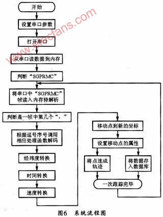
The software design flow chart of this system is shown in Figure 6.
3.3 Test
After the software is written, it should be compiled with gcc on the PC first. There is generally no big problem in the compilation process. Then, you can connect the completed GPS receiver to the PC through the serial port to debug the software and hardware. The GPS machine of this design has no problems after running for a few days and is very stable. However, the ultimate purpose of making this demo board is to design a handset based on ARM9 processor. Therefore, the author cross-compiles the software. The compiler used is arm-linux-gcc version 3.3.2. In order to verify the feasibility of the test board and software under the embedded system, the author also connected it to the S3C2410 experiment box produced by Guangzhou Friendly-arm and tested it. The test results are very stable and the positioning is very accurate.
4 Conclusion
The main purpose of designing this hardware and software is to prepare for the GPS selection of a handheld navigator. The results show that the system designed with this type of GPS and this software is very stable. The positioning is fast, and the first positioning is only 8s under hot start conditions; when it is cold start. The first positioning time is only 45s, and the positioning accuracy is 10m, which is the highest accuracy in the current civil GPS; and it can design beautiful products without affecting the function. The designed software can completely receive the GPS positioning information through the GPS receiver, and has greater flexibility. If you switch to an electronic map of another coordinate system, you can add a coordinate system conversion module before the trace. The processed data plays an important role in high-level decision-making and can be widely used in navigation, track playback, central vehicle monitoring and scheduling, etc.
The Win3 flashlight is built of high quality aerospace technological aluminium . Sturdy and durable enough for long time using. IP 68 water proof, IECEX standard explosion proof design suitable for any hazardous environment and adverse weather conditions .
High quality LED ensures 50000 hours long life span and 500 battery cycles, which largely reduce the ownership cost.
The battery capacity up to 4400mAh providesyou a long outdoor working time, that is about 14 hours(normal illumination) or 6 hours(highillumination)
Led Torch Light,Solar Torch Lights,Mobile Torch Light,Rechargeable Torch
ZHEJIANG HUACAI OPTIC-TECHNOLOGY CO LTD , https://www.win3safety.com