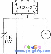
The color display power circuit is one of the most common areas where faults occur. In the past, many display power circuits used the UC3842 chip from the US. However, in practice, it has been found that the UC3842 is more prone to damage. To determine whether the chip is working properly, you can connect a DC voltage of 16–18V to the UC3842. Specifically, apply the positive voltage to pin 7 and the negative to pin 5. Then, use a multimeter set to voltage mode to measure the voltage between pin 8 and pin 5. If the reading is 5V, the chip is functioning correctly. If not, the power module may be damaged.
If you have access to a breadboard or digital logic lab setup, you can easily test the UC3842 without soldering. Simply plug the chip into the breadboard and perform the test, which makes the process more efficient and avoids damaging the IC pins. The testing method is illustrated in the diagram below.
Auto Rotation Cleaver,High Precision Optical Fiber Cleaver,Optical Fiber Cleaving,Auto Fiber Cleaver
Guangdong Tumtec Communication Technology Co., Ltd , https://www.gdtumtec.com