This article introduces in more detail the low-power transmitting circuits in the 88~108MHz FM broadcasting range that are easy to produce in a few amateur situations, including simple single-tube transmitting circuits and stereo transmitting circuits using integrated circuits. . Mainly used for FM wireless headsets, telephone wireless recording and forwarding, remote control, wireless alarm, monitoring, data transmission and campus FM radio.
Mono frequency modulation transmitting circuit
This article refers to the address: http://
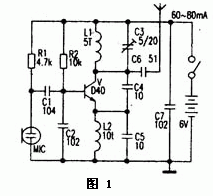
Figure 1 is a more classic 1.5km single-tube FM transmitter circuit. The key components in the circuit are the Transistor, which uses D40, D5O, 2N3866 and so on. The working current is 60--80mA. However, the above triodes are difficult to purchase, and the price is higher, and there are more fakes. The author chose other triode experiments, the relatively easy to buy triode C2053 and C1970 is quite good, the actual line-of-sight communication distance is greater than 1.5km. I have also replaced the D40 tube with the ordinary transistor 8050. The working current is 60--80mA, but the emission distance is less than 1.5km. If it is changed to 9018, the working current is smaller and the emission distance is shorter. In addition to the transmitting transistor; the choice of the parameters of the coil L1 and the capacitor C3 is more important, if not selected properly, the vibration will not work or the operating frequency will exceed the range of 88--108 MHz. Among them, L1 and L2 can be wound with a 0.31mm enameled wire on a round bar of about 3.5mm in a single layer of 5åŒ and 10åŒ, and C3 is made of a 5-20pF porcelain or polyester adjustable capacitor. In actual production, the capacitor C5 can be omitted, and the L2 can be replaced with a 10-100 mH ordinary inductor. If the launch distance is only a few tens of meters, then the battery voltage can be selected to be 1.5-3V, and the D40 tube can be replaced with a cheap 9018, etc., and the power consumption will be less. See also "Electronic News", No. 8, 2000 The fifth edition (simple long-range wireless FM microphone) was slightly modified after the article. The single-tube transmitter introduced in Figure 1 has the characteristics of simple circuit, large output power and easy production. However, it is inconvenient to connect the high-frequency cable to send the RF signal to the outdoor transmitting antenna. Generally, the 0.7--0.9m lever is used. The antenna is directly connected to the C5 for transmission. Due to the Doppler effect, when the person moves around the antenna, the frequency drift phenomenon is very serious, so that the receiver sound that is normally sounded is distorted or silent. If the transmitter is used as a wireless microphone, it is conceivable how severe the frequency drift is when the antenna is pinched.
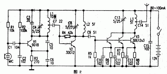
Figure 2 shows the 2km FM transmitter circuit. This circuit is divided into three levels of oscillation, frequency multiplication and power amplification. In the circuit, V1, C2--C6, R2, R3 and L1 form a three-point capacitor oscillator. The oscillation frequency is mainly determined by the parameters of C3, C4 and L1. The oscillation frequency is 44~54MHz. The signal is from the center tap of L1. The output is coupled to V2 amplification through C7, and the double frequency signal of 44~54MHz is selected by C8 and L2, namely 88-108MHz. This signal is amplified by C9 coupling to V3, and V3 is composed of 3 3DGl2 transistors in parallel. Can increase the output power. When the circuit is working normally, the current is about 80-100 mA. The three 3DG12s that make up V3 can be fitted with appropriate heat sinks to prevent overheating. During production, L1~L3 is wound on a single layer with a 0.31mm enameled wire on a 3.5mm diameter round bar.
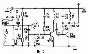
Figure 3 is a practical 50m FM wireless headset transmitting part of the circuit. The circuit is divided into an oscillation and signal amplification section. L1, C2-C5, V1 and other improved capacitor three-point oscillators similar to the black-and-white TV high-frequency head local oscillator circuit, good frequency stability, long-term work does not run frequency, practice has proved that in amateur situations, the improvement is adopted. The capacitive three-point oscillator is fully capable. The author used a soldering iron to directly solder the collector of V1 for a few seconds. When the temperature of the triode is very high, the reception with the ordinary radio is still normal, and there is no running frequency phenomenon. The frequency of the oscillator is mainly determined by L1 and C2. By fine-tuning L1, it can cover the range of 88-108MHZ. The audio signal is coupled to the base of V1 via R6 and C11. The capacitance between the e and b poles of V1 changes with the frequency of the audio voltage to achieve frequency modulation. In this circuit, L, ~L3 are wound in a single layer on a 3.5mm round bar with a 0.31mm enameled wire.调整 Adjust the L1 turn spacing to fine-tune the oscillation frequency, and then fine-tune the inter-turn spacing between L2 and L3 to obtain the maximum output power.
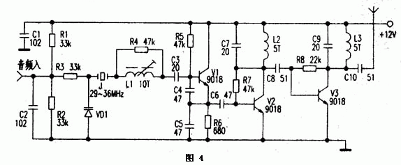
Figure 4 shows a crystal oscillator transmitter circuit. J. in the circuit VD1, L1, C3~C5, and V1 form a crystal oscillation circuit. Since quartz crystal J has good frequency stability and is less affected by temperature, it is widely used in cordless telephones and AV modulators. Vl is a 29~36MHz crystal oscillatory triode. The emitter output is rich in harmonic components. After V2 amplification, the 3rd-frequency signal (ie 87~108MHz) is selected in the network where the collector is composed of C7 and L2 and is resonant at 88-108MHz. The signal is the strongest, and then amplified by V3; L3, C9 select the frequency to get the ideal FM band signal. The process of frequency modulation is such that the change of the audio voltage causes a change in the capacitance between the electrodes of VD1; since the VD1 is connected in series with the crystal J, the vibration frequency of the crystal also changes slightly. After the triple frequency, the frequency offset is 29-36 MHz. 3 times the crystal frequency offset. In practical applications, in order to obtain a suitable degree of modulation, a quartz crystal or a ceramic vibrator having a large modulation frequency offset may be selected, or a slightly complex 6-12 frequency multiplying circuit may be used. If the input audio signal is weak; a voltage amplification circuit can be added.
Since the 1.5km FM transmitter (see Figure 1) uses a capacitor three-point oscillator, when the antenna parameters are slightly changed, the running frequency phenomenon will occur. Furthermore, since it is a single-tube self-oscillation, the operating current is large, when working. After a few seconds to a few minutes, the temperature rise of the triode causes a change in the inter-electrode capacitance, which also causes a change in the oscillation frequency (generally, the oscillation frequency is lowered), and sometimes the frequency drift is as high as 0.2--1 MHz. When used as an FM radio or remote remote alarm, the work reliability is poor, but the components are few, the cost is low, and the debugging is easy. It is suitable for junior enthusiasts to conduct experiments. 2km
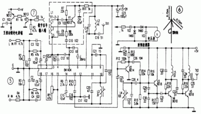
The FM transmitter (see Figure 2 in the previous issue) uses three-stage circuits of oscillation, frequency multiplication and power amplification. The stages are relatively independent. The stability of the frequency is better than the 1.5km transmitter of the single-tube self-oscillation, but it is turned on for several minutes. After that, there is still a frequency drift of 0.2-0.4MHz, which is mainly due to the large operating current of V3, the temperature rises, causing the change of the inter-electrode capacitance. This change causes the resonant network parameters composed of C8 and L2 through C9. The change, coupled with the increase of V2 temperature, also causes the resonance network parameters composed of C8 and L2 to change. This change is transmitted to the main vibration level composed of C3, C4, L1, C5, C6, V1, etc. through C7, and finally makes the oscillation frequency. It also changes (in general, the oscillation frequency is also reduced). During the experiment, the heat dissipation of the triode can be enhanced, the interstage coupling can be reduced, the capacity of C9 and C7 can be reduced, and transistors, resistors and capacitors with less influence on temperature can be selected. Wait, but the frequency drift is still serious. In the wireless earphone transmitter shown in Figure 3 of the previous period, since the improved capacitor three-point oscillator is used, the frequency of the transmitter shown in Fig. 1 and Fig. 2 is stable, and the fidelity requirements of the television wireless earphone are not very high. The occasion is very suitable. The crystal oscillator transmitter shown in Figure 4 above has a good frequency stability due to the use of a crystal. However, when used in FM radio and wireless headphones, the frequency offset of the modulation is much smaller than that of the LC oscillator. When the volume is small, the sound is not round, and it is generally more suitable for circuits such as cordless phones and walkie-talkies with smaller frequency deviations. Sound vibrators have been widely used in transmitters of various wireless remote control and wireless data transmission equipment, but acoustic vibrators with frequencies between 88 and 108 MHz are difficult to purchase, and various frequency synthesis transmitters with excellent performance are more troublesome. Those who are interested can refer to the article (Electronic Report), No. 41, No. 41, 2000 (analysis of the modulation unit circuit of the digital frequency synthesizer of TGF-10 FM radio transmitter), which is used by the general-purpose Motorola frequency synthesizer. As the core of the chip MCl45152P, a high stability frequency of 84~108MHz can be obtained by an external DIP switch. FM stereo transmitter (see Figure 5) The core device of this circuit is the stereo dedicated chip BA1404. Many FM stereo modules are made by encapsulating the BAl404 and peripheral components in a plastic or metal casing. Only the power input, audio input, and RF output leads are exposed. As long as you understand the BAl404, you know what is inside the FM stereo module. . A stereo audio signal from a sound source is coupled to BAl 404 via a network of R1, R2, R5, C1, C3, C5 (R4, R3, R6, C2, C4, C6). The left (right) channel of the IC is amplified, and then balanced modulation is performed. The modulated composite signal is output from the 14th pin of the IC, and the pilot signal on the 13th pin is composed of B9, C15, B10, C16, and C17. The network is mixed, the mixed signal after mixing enters the 12-pin of the IC, the contrasting 8, 9, 10 feet, C20--C22 and the three-point oscillator composed of the core are frequency modulated, and the IC 10 is modulated on the 10 feet. The RF signal is internally amplified and output from the 7th pin, and is selected by C18 and L2 and sent to the antenna TX1. To achieve FM stereo, the 5 and 6 feet of the BAl404 need to be connected to a 38 kHz crystal. However, it is difficult to purchase a dedicated crystal of 38 kHz during amateur production. Therefore, in the absence of the crystal, the circuit in the dotted line can be used to make a discrete component. A 38kHz oscillator, the 38kHz signal is sent to the fifth pin of the IC via R8 and C10. At the time of production, Ll can use the radio intermediate frequency transformer ITF—2—1, TTF-2-2 or TFF-2-9, etc., and pay attention to the connection of the pins. Do not make a mistake. 3 feet are grounded, 2 feet are connected to the emitter of V1, 1 The feet are feedback and output feet. A 38 kHz signal with a relatively stable frequency and a sufficiently high amplitude can be obtained by adjusting its core. It is particularly noteworthy that C8 should choose a 0.33uF polyester capacitor. It is not suitable to choose a ceramic capacitor because the stability of the ceramic capacitor is poor, and the oscillation frequency is unstable, and the FM stereo is not working properly. Since the high-frequency sag of BAl404 is a three-point capacitor oscillator, the stability of the frequency is poor. Therefore, the circuit does not use the original high-frequency oscillator, and the method of using an improved capacitor three-point oscillator with a stable external frequency can satisfy the amateur. FM radio and FM wireless headset requirements. For example, the transmission part of the ZN-2001 FM stereo wireless earphone uses an improved three-point oscillating circuit for the capacitor. After the stereo composite signal is amplified by the V2 voltage, the frequency modulation is realized by directly adding C26 and R14 to the base of V3. Its characteristic is that according to the needs of users, the inductance of L4 can be adjusted outside the casing with a screwdriver, so that it can be freely adjusted within the range of 88~108MHz, avoiding the frequency of local FM radio stations. Another feature of the machine is that there is a 1--5W power extension on the circuit board. If the campus broadcasts, the components of the part can be installed and can be put into use after debugging. However, it is worth noting that if the wireless earphone is still transmitting with the whip antenna on the machine after increasing the power, the strong RF signal will generate its own interference; the sound is distorted, there is hum or no sound, so it must pass 50 The European-specific communication cable transmits RF signals outdoors. In the installed power extension part of the shot, the RF detector can be used to adjust the resonance state of each stage. Connect the input end of the RF detector (one end of the 1k resistor) to the collector of the preamplifier transistor, adjust the inductor on the collector, make the voltage at the output of the RF detector the highest, and then step backwards in the same way. Level adjustment, then detect the antenna end, and finally adjust the inductance coils of each level to make the output voltage the highest, that is, complete. Compared with infrared wireless headphones, the host (transmitter) of the FM stereo wireless headset can be used normally between the host and the receiver, while the infrared headset cannot. In addition, the ordinary infrared headphones have no stereo function, so the FM stereo wireless headphones are more suitable, and when listening to music, it is more pleasant. If an outdoor antenna is installed, even a very weak RF signal can travel far, so making a good antenna is much more efficient than simply increasing the transmit power. It is cumbersome to make a horizontally polarized, omnidirectional transmit antenna, and the general FM radio station also adopts horizontal polarization. In order not to cause interference, the author introduces a simple assembly and high efficiency vertical. Polarized antenna. Since the earphone cable is used as the radio antenna when moving, the earphone cable is vertical; the antenna of the car radio is also approximately vertical, so vertical polarization is more suitable for mobile reception. The antenna adopts a 50-ohm umbrella antenna for the communication machine. As shown in Fig. 6, there are 4 or 7 vibrators on the antenna base, each of which is about 0.75 m long. The vertical one is the main vibrator of the transmitting antenna, and the antenna is oblique. The downward three or six vibrators form a simulated ground, and the angle between them is uniform. The angle between the main oscillator and the vibrators that make up the simulated ground is also fixed as required. The impedance of the whole antenna is 50 ohms. The gain in the 10MHz bandwidth is about 2dB, and the standing wave is less than 1.2. In many cases, the digital signal is transmitted, so the circuit of the field 7 can be referred to, and several components can be added to realize the wireless digital transmission of the transmitter.
Pengchu is one of the factory made Switching Power Supply for 12 years old,and the Power Supply from 5-500w,output voltage from 5v-48v,all of our Power Adapter with new brand material,we have experience engineer to study and develop,all our Dc Power Supply are get to CE,FCC and ROHS sandard and approved,some power supply are UL and ETL approved,also our power supply built with over load protection,over temperature protection,over current protection.therefore, the quality of the switching power supply is guaranteed,We insist on quality as our standard and service as our tenet to develop our company.
32V Power Supply,Power Supply 32V Output,Oem Power Supply For Cctv Camera
Shenzhen Pengchu Industry Co., Ltd , https://www.pc-adapters.com