What is spread spectrum communication technology? Spread Spectrum Communication (Spread Spectrum CommunicaTIon) is abbreviated as spread spectrum communication, which is characterized by the bandwidth used to transmit information is much larger than the bandwidth of the information itself. Spread spectrum communication technology uses spread spectrum coding for spread spectrum modulation at the origin, and receives information at the receiving end with relevant demodulation technology. This process has many excellent features. Spread spectrum communication technology is a kind of information transmission mode, and the bandwidth occupied by the signal is much larger than the minimum bandwidth necessary for the transmitted information; the expansion of the frequency band is completed by an independent code sequence, which is realized by the method of coding and modulation. It has nothing to do with the transmitted information data; at the receiving end, the same code is used for synchronous reception, despreading and restoring the transmitted information data.
The spread spectrum communication technology performs spread spectrum modulation at the transmitting end with spread spectrum coding, and receives the signal at the receiving end with the relevant demodulation technology. Since spread spectrum communication is spread spectrum modulated transmission using spread spectrum coding, and signal reception needs to be obtained by correlation despreading between the same spread spectrum codes, this provides a basis for frequency multiplexing and multiple access communication. Fully utilizing the correlation characteristics between the spreading codes of different patterns and assigning different spreading codes to different users, the signals of different users can be distinguished, and the frequency multiplexing can be realized without interference from other users.

Spread spectrum communication technology is an information processing transmission technology. Spread spectrum communication technology is a technique of spreading a signal to a plurality of carrier frequencies by using a code that is independent of the transmission data (information) in the same domain. Make it take up far less than the minimum bandwidth necessary to transmit information. Spread spectrum communication technology can provide more secure transmission, and can reduce interference and improve frequency band utilization. The spread spectrum technology is used to add the jitter processing to the clock frequency, so that the transmission frequency is no longer concentrated at one frequency point, and the electromagnetic interference can also be reduced.
There are three main methods for commonly used spread spectrum techniques, namely direct sequence spread spectrum, frequency hopping spread spectrum, time hopping spread spectrum, and linear modulation . However, in the process of actual use, their mixing is often used.
Spread spectrum communication technology features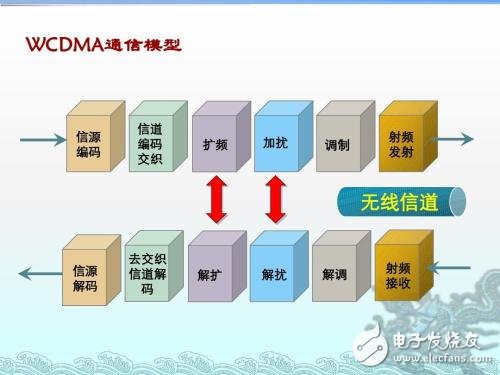
The spread spectrum communication system has the following two characteristics:
(1) The bandwidth of the transmitted signal is much larger than the bandwidth of the original information signal being transmitted;
(2) The bandwidth of the transmitted signal is mainly determined by the spreading function, which is usually a pseudo-random (pseudo-noise) encoded signal.
The above two features are sometimes referred to as criteria for judging a spread spectrum communication system.
The biggest feature of the spread spectrum communication system is its strong anti-human interference, anti-narrowband interference and multi-path interference resistance.
Advantages and disadvantages of spread spectrum communication technology
Communication systems using spread spectrum technology have the following advantages:
(1) Good anti-interference performance, it has strong anti-human broadband interference, narrow-band aiming interference, relay-and-forward interference, and is beneficial to electronic opposition. If adaptive cancellation, adaptive antenna, and adaptive filtering are used, multipath interference can be eliminated, which is advantageous for military and civilian mobile communications.
(2) The concealment is strong and the interference is small. Since the signal is spread over a wide frequency band, the power per unit bandwidth is small, that is, the signal power spectral density is very low. The signal is submerged in white noise, it is difficult to find the existence of the signal, and with the spread spectrum coding, it is more difficult to pick up the useful signal. Spread spectrum communication technology broadens the bandwidth of the transmitted signal, thereby reducing the "flux density" of the system in the unit bandwidth, which is good for space communication.
(3) It is easy to implement code division multiple access, and spread spectrum communication occupies broadband spectrum resources, improves anti-interference ability, and improves frequency band utilization.
Disadvantages of the spread spectrum system:
(1) The frequency bandwidth used by the system.
(2) Compared with FDMA and TDMA multiple access methods, the CDMA multiple access method using spread spectrum technology is more complicated in mobile communication systems.
Future Bus connectors Description
Future Bus connectors, which use 2mm style have a mating distance of 10mm. Both Future bus and the upgrade Future bus+ are out-dated.No additional work has been done to upgrade the specification over the years. However we still produce products which meet the Physical and Electrical layers of IEE P896.
Antenk future bus connecto feature
designed in metric dirnension on 2 millimeters grid over 5 rows.
1 Standardized product through EIA (USA), IEC and CECC (international).
2 Selected by IEEE as the interconnection system for Futurebus + / SCI / VicBus.
3 Multi-sources product,use for telecommunication, network, server / workstation market.
4 High tempersture materials SMT compatible.
5 Modular design giving flexibility for system design.
6 Stackable end to end without loss of contact position.
7 High density (more than 2 times as compared to the standard inch based " Euroconnector DIN 41612" ).
8 Tuning Fork female contact concept for higher robustness and improved reliability
(low contact resistance and high normal force).
9 Low insertion force design.
10 Inverse connector system (signal and power).
11 Optimized solder and compliant press-fit terminations for backplane and circuit board connectors.
12 differents mating lengths on signal and 3 on power for standard connector system.
Future Bus connectors Application
Telecom backplane board
Antenk offers a complete line of 5+2 and 8+2 Hard Metric Connectors as well as a complete line of 4 and 5 row Future bus Connectors.

4 and 5 row Future bus Connectors
4 Rows Signal & Power
5 Rows Signal & Power
Female IDC Type 4&5 Rows
Power Connector & Cable
Shroud
Vertical, 5 Rows
Right Aangle, 5 Rows
Vertical, 4 Rows
Right Angle, 4 Rows
5+2 and 8+2 Hard Metric Connectors

2.0mm Future Bus Connector Male DIP
2.0mm Future Bus Connector Female DIP
2.0mm Future Bus Connector Male Press Fit
2.0mm Future Bus Connector Female Press Fit
2.0mm Future Bus Connector Power Type
2mm HM (hardmetric) Connector Introduction
System designed to meet the current and future needs of instrumentation applications giving excellent electrical and mechanical characteristics. It is a high performance, high density system with flexible configuration which offers upgradeability. The connector system is fully supported by Antenk spice models to guarantee choosing the right product to match the application.
ANTENK 2.0mm HARD METRIC CONNECTOR MODULES comply with international IEC 917and IEC 61076-4-101
standards. The connector systems in telecommunication and other industries require hight density connectors to support
larger amounts of data increasingly higher speeds antenk 2mm hardmetric modules offer the solution
Features and Benefits:
This high density connector modules can be stacked end to end without loss of space.
1,ANTENK developed the 2.0mm series under thorough consideration of impedance match, propagation delay,
cross talk, reflection. It is the ideal connector for digital high speed data application.
2,ANTENK offers differend types with inverted mating configuration. The male connector is a fixed module at the
backplane and the female commector is a free component of the plug-in module. The male connector has 5 signal row.
3 The outer shielding rows z and f of the male connector engage the shielding contacts of the famale connector. theshield
is also designed for gas tight, press-fit installation.
4 The connector system offers 15 contact length that utilize the proven press-fit assembly technique. Within the 15
contact length are 3 mating levels, achievable on both the plug-in and rear I / 0 side.
5 Coding system prevents mix-up and wrong mating between male and female connectors.
6 The 2.0mm hard metric connectors and DIN 41612 connectors can be used on the same PC board as both have the
same mating distance.
7 Staggered make-break pin populations for optional hot-swap capability.
8 Rear pin option for through-the-backplane I/O application.
9 High density PCI capability,shield for EMI/RFI protection.
2mm HM (hardmetric) Connector Features:
High density system with small real estate on backplane and daughtercard
Extensive range of signal, power, coaxial and fibre board-to-board and cable-to-board connections
Modular units give flexible configuration
Special versions for VME64 extensions and CompactPCI
Signal contact rating 1.5a fully energized
Universal power module rated at 7.8A/line, 23.4A fully energized
All lines impedance controlled to 50 (single ended) and 100Ω (differential) nominal
Safe design, complies with IEC950 in mated condition
Universal power module is safe in unmated condition
Several performance levels for board and cable connectors with unshielded and shielded versions
Mismatching keys block mating before any contact touch
Small press fit board hole allows maximum track width and minimum signal corruption
1.4 to 5.6mm (0.055 to 0.220 inch) Backplane thickness range
2mm HM (hardmetric) Connector Applications
Communications & Networking, Computers & Computer Peripherals, Sensing & Instrumentation
Metric Connectors,2.0Mm Hard Metric Connectors,Hard Metric Connectors,Hard Metric Female Connector,2.0mm Future Bus Connector Male DIP,2.0mm Future Bus Connector Female DIP
ShenZhen Antenk Electronics Co,Ltd , https://www.pcbsocket.com