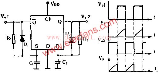
As shown in the figure is an unsteady circuit composed of D flip-flops. The unsteady circuit has no steady state and it automatically flips in two states 0 and 1.
Discharge quickly and prepare for the next charge. In addition, the high level of the Q terminal is charged to C2 through the resistor R2, so that the potential of the R terminal is gradually increased. After the time T2=0.69R2C2, the potential of the R terminal reaches the reset level VDD/2, so that the flip-flop turns over and the Q terminal becomes High level, Q end becomes low level. Complete an oscillation cycle. The above process is repeated repeatedly to form a self-oscillation.
With the rapid development of mobile communication equipment, in the mobile communications network engineering design, according to the requirements of the network coverage, traffic distribution, anti-interference requirements and network service quality and so on the actual situation to select the base station antenna, the communication base station antenna is currently on the market work the characteristics of the narrow frequency band, such as directional literal outdoor antenna, The operating frequency band is 860~960Mhz. Those multi-band antennas have the characteristics of high manufacturing cost and complex structure. With the development of communication technology, especially the popularization of 3G communication technology, such antennas are difficult to meet the market requirements. Therefore, to avoid the above problems, it is necessary to provide a base station antenna that is simple to manufacture, low cost, and reliable in performance to overcome the alleged defects in prior art.
Outdoor Antenna for TV ,Outdoor Antenna for WiFi,Outdoor Antenna for Booster ,Outdoor Antenna for Router ,Waterproof outdoor Antenna
Yetnorson Antenna Co., Ltd. , https://www.yetnorson.com