Circuit Operation Principle The electric pulse therapy device circuit consists of a power supply circuit, a low frequency oscillator, a frequency division control circuit, and a pulse voltage generation circuit, as shown in Figure 9-10. 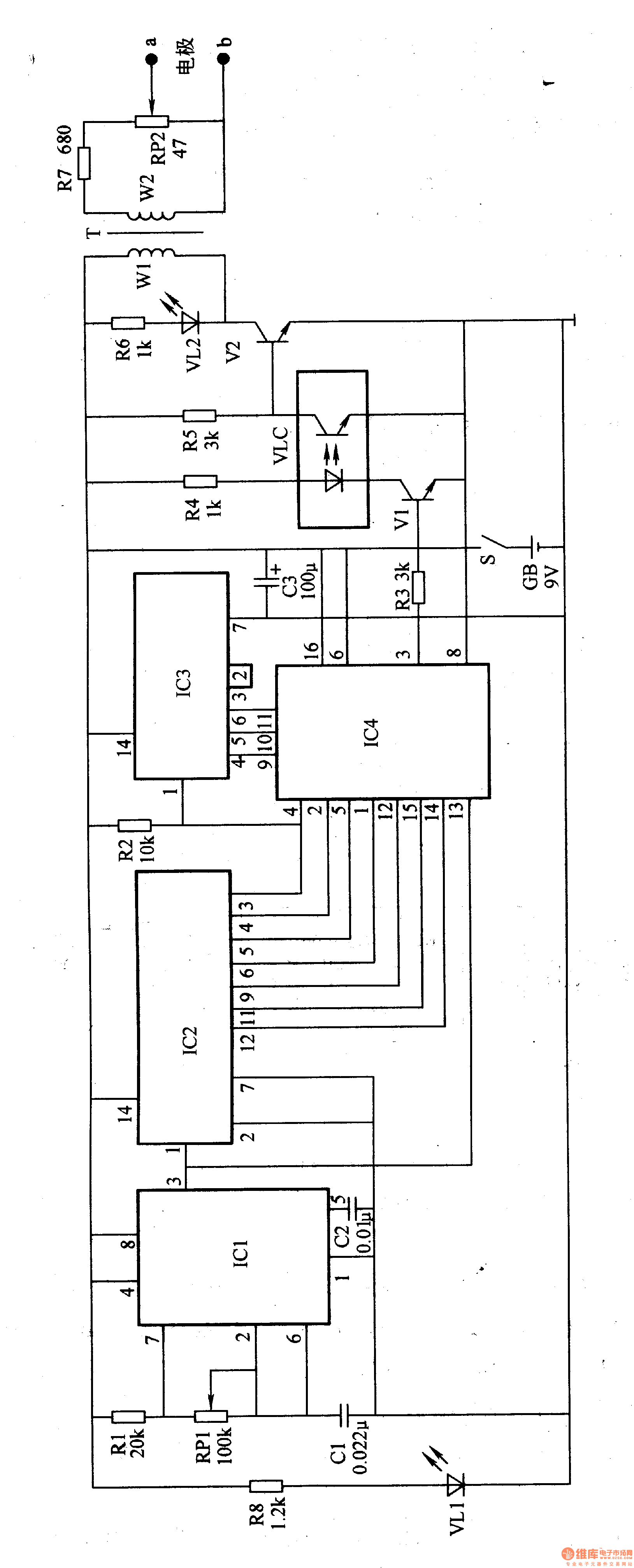
The power circuit is composed of a power switch S, a battery GB, a filter capacitor C3, a current limiting resistor R8, and a power indicating LED VLl.
The low frequency oscillator circuit is composed of a resistor R1, a potentiometer RP1, capacitors C1, C2, and a time base integrated circuit ICl.
The frequency division control circuit is composed of a counting frequency divider integrated circuit IC2, 1C3, an electronic switch integrated circuit IC4, resistors R3, R4, a transistor Vl, and a light emitting diode inside the optical coupler VLC.
The pulse voltage generating circuit is composed of resistors R5-R7, LED VL2, transistor V2, photo transistor inside VLC, pulse transformer T, potentiometer R-tooth and electrodes a, b.
Turn on the power switch S, GB provides 9V working voltage for the low frequency oscillator, the frequency dividing control circuit and the pulse voltage generating circuit, and also VLl after the R8 current limiting step-down.
The low-frequency oscillator oscillates after power-on, and outputs a low-frequency pulse signal with a frequency of 256 Hz from pin 3 of IC1. After the low frequency pulse signal is processed by the IC2 and 1C3 frequency division control, the pulse signal of 2-256 Hz change is output from the 3 pin of IC4 (in 8 steps, it is automatically incremented or decremented by a multiple of 2 Hz, and the interval period of each file is 8 s) V2 is controlled by Vl and VLC, and V2 is intermittently turned on and RP2 is adjusted, and then acts on the acupuncture points or the painful parts of the human body through the electrodes a and b.
Adjusting the resistance of RPl can change the oscillation frequency of the low frequency oscillator.
Adjusting the resistance of RP2 can change the stimulation intensity of the electric pulse to the human body.
Component selection
Rl-R8 uses 1/4W carbon film resistor or metal film resistor.
RP1 uses a small synthetic carbon film potentiometer; Rå¨ uses a small synthetic carbon film potentiometer with a switch (power switch S).
Cl and C2 use monolithic capacitors or polyester capacitors; C3 uses electrolytic capacitors.
Both VLl and VL2 use high-brightness light-emitting diodes of φ3mm.
Vl selects S9013 type silicon NPN transistor for use; V2 selects 3DKl04 type silicon NPN transistor for use.
ICl selects NE555 type time base integrated circuit; IC2 and 1C3 select CD4024 or MCl4024 type binary pulse count/divider integrated circuit; IC4 selects CD405l or MCl4051 type eight-bit electronic switch integrated circuit.
VLC uses 4N25 or 4N35 optocouplers.
T selects the power transformer with lW and secondary voltage of 3-5V. When using, the secondary winding is used as the winding W1 of T.
The electrodes a and b can be made of two pieces of φ4Omm phosphor bronze (the gauze is wrapped on the outside and should be immersed in salt water or liquid medicine for conductivity).
GB uses 9V laminated battery or small DC regulated power supply.
ShenZhen JunJin Technology Co.,Ltd , https://www.jjtcl.com