[Photo] Highly sensitive wireless microphone

Here we introduce a highly sensitive wireless FM microphone, which can pick up the weak sound within 5 meters, and the transmission distance can reach about 500 meters. Its working frequency is in the range of 88 ~ 108Mhz, and its transmitted signal can be received through FM radio. Another feature of this wireless microphone is that the operating frequency is very stable, even if you touch the transmitting antenna with your hand, it will not cause changes in the transmitting frequency. It can be used for home entertainment, baby sleep monitoring and indoor and outdoor sound monitoring.
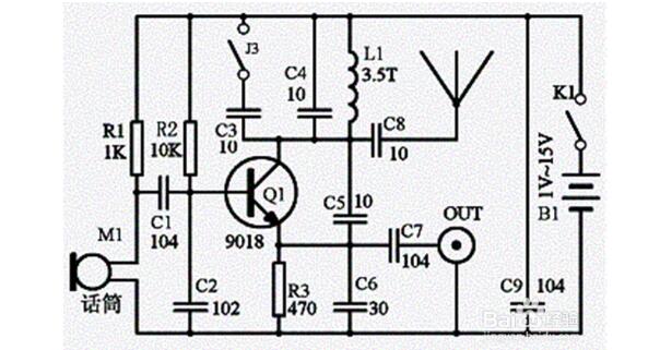
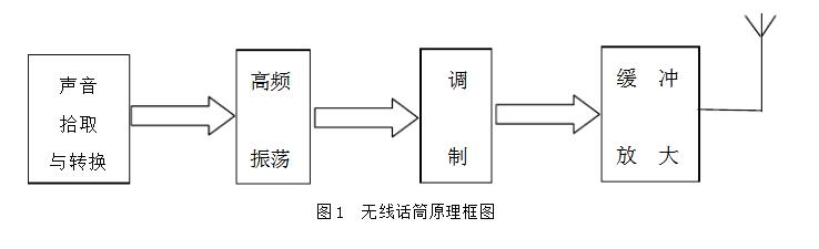
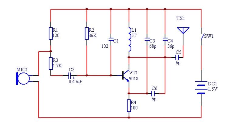
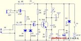
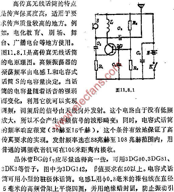
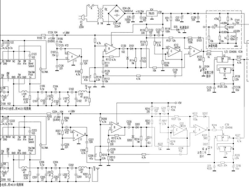
Circuit principle The circuit of the highly sensitive wireless microphone is shown in the figure. The circuit is composed of acoustic-electric conversion, pre-emphasis circuit, audio amplifier circuit, modulator and high-frequency power amplifier.
The acoustoelectric converter is served by an electret condenser microphone. He picks up the acoustic signal of the surrounding environment and outputs the corresponding electrical signal. After C1, it is sent to the pre-emphasis circuit composed of R2 and C2 for bandwidth compression to improve the quality of voice modulation (Corresponds to de-emphasis in FM radio). VT1 is an audio amplifier that amplifies the pre-emphasized audio signal and sends it to the base of VT2 through C3 for frequency modulation. VT2 constitutes a common base ultra-high frequency oscillator, the voltage of the base and collector changes with the change of the audio signal input from the base, so that the junction capacitance of the base and collector changes, and the frequency of the high-frequency oscillator also changes with Change to achieve frequency modulation.
VT3 constitutes a class C high-frequency power amplifier with emitter output, which has two functions: one is to increase the transmission power and extend the transmission distance; the other is to isolate the antenna from the oscillator and reduce the influence of the antenna on the oscillator oscillation frequency. The signal after the high-frequency power amplifier is output by the emitter of VT3, and sent to the antenna through C10 and L3 for transmission. L3 is the antenna plus sense coil, used when the length of the antenna is less than one-quarter wavelength to improve the antenna's transmission efficiency. The capacity of C8 and C10 can not be greater than 20PF, otherwise the change of the antenna will cause frequency instability.

Component selection and production VT1 can use 9014, VT2 can use 9018, require magnification greater than 80; VT3 selects 8050C or 3DG12C, requires magnification greater than 50.
C1, C3, C11 use electrolytic capacitors, C4 ~ C10 are ceramic capacitors, resistors use carbon film resistors, L1 ~ L3 with a diameter of 0.4mm enameled wire around the ballpoint pen core 6 turns, and then removed from the tire. L1 should be tapped at the 3rd place, and L2 and L3 should be arranged vertically on the printed circuit board. The antenna is best used as a whip antenna, but it can also be replaced with a plastic cord that is 800 mm long.
The printed circuit board diagram is as follows (click to enlarge). Note: There is no switch S on the printed circuit board, which needs to be connected separately.


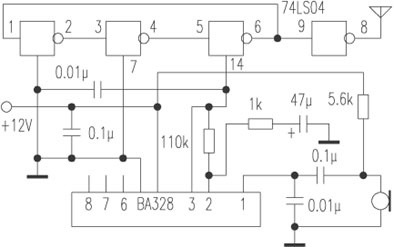
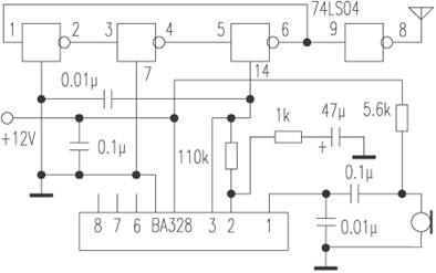
After the circuit is installed, it needs to be debugged. The debugging can be carried out in three steps:
1. Adjust the working points at all levels: adjust the resistance R3 to make the collector voltage of VT1 to 1.5V (or the collector current is about 1 mA); adjust the resistance R7 to make the collector current of VT2 to about 4 to 6 mA, At this time, touch the collector of VT2 with tweezers. This current should change significantly, indicating that the high-frequency oscillator is working properly. The working point of VT3 does not need to be debugged.
2. Frequency adjustment: Turn on the FM radio and search for the local signal in the range of 88 to 108Mhz. If the frequencies of the two devices are aligned, a strong howling sound will be generated in the radio. At this point, the frequency used by the local FM radio station should be avoided. The method of avoidance is to use a small screwdriver to move the turn of the coil L1.
3. Commissioning of launching field strength: first make a simple field strength meter, the circuit is shown below. Connect the two points A and B of the field strength meter to the antenna end and ground end of the wireless microphone, and fine-tune the turn distance of L2 and L3 of the wireless microphone, so that the multimeter reading of the field strength meter can be maximized. The field strength meter multimeter should be placed in the DC 10V or 50V file.
The adjusted circuit can be put into use.

In-depth analysis of the first-level cache and second-level cache of the technical zone CPU eMMC mass burning dilemma, do you really know? Isolation flyback and non-isolated BUCK application design plan Schottky barrier diode selection and application guide How to use Altium in program design Designer puzzle?

Follow WeChat

Interesting and informative information and technical dry goods

Download Audiophile APP

Create your own personal electronic circle

Follow the audiophile class

Lock the latest course activities and technical live broadcast
Collect People collection
share it:
comment
Publish

related suggestion

Simple wireless microphone circuit diagram (seven wireless microphone circuit diagrams)

This article introduces the circuit diagram details of seven wireless microphones. The electronic component microphone (microphone) on the circuit board first turns the natural sound signal into an audio electrical signal, ...

Published on 2018-01-25 16:35 • 1661 views
Simple wireless microphone circuit diagram (seven wireless microphone circuit diagrams)
Wireless microphone circuit design scheme summary (multiple circuit design principles in detail)

This article introduces the wireless microphone circuit design and schematic diagram. The wireless microphone circuit consists of a sound pickup circuit, a sound conversion circuit, a high frequency oscillator, and modulation ...

Published on 2018-01-25 15:14 • 501 times read
Wireless microphone circuit design scheme summary (multiple circuit design principles in detail)
9018 wireless microphone circuit diagram (four wireless microphone circuit diagrams)

This article introduces the circuit diagram of four 9018 wireless microphones. The wireless microphone is composed of several pocket transmitters (which can be installed in the pocket and the output power is about 0.0 ...

Published on 2018-01-25 14:13 • 576 times read
9018 wireless microphone circuit diagram (four wireless microphone circuit diagrams)
1.5v battery wireless microphone production (six wireless microphone circuit diagram production ...

The wireless microphone is composed of several pocket transmitters (which can be installed in the pocket and the output power is about 0.01W) and a centralized receiver. Each pocket sends ...

Published on 2018-01-25 13:40 • 908 views
1.5v battery wireless microphone production (six wireless microphone circuit diagram production ...
The difference between U-segment and V-segment wireless microphones and the better solution of U-segment than V-segment ...

The V segment does interfere with each other when multiple sets of wireless microphones are used. Of course, it cannot be said that the U segment does not, but it has a large extension range and can be adjusted as much as possible ...

Published on 2018-01-19 10:11 • 782 views
The difference between U-segment and V-segment wireless microphones and the better solution of U-segment than V-segment ...
bomo cloth wood T series one drag two wireless microphone

Published on 2017-11-14 09:50 • 327 views
bomo cloth wood T series one drag two wireless microphone
What brand of wireless microphone is a good leading brand

Published on 2017-11-13 10:28 • 261 times read
What brand of wireless microphone is good, leading brand
Questions and answers about the use of infrared wireless microphones in KTV private rooms

Published on 2017-11-10 11:25 • 249 views
Questions and answers about the use of infrared wireless microphones in KTV private rooms
Under what circumstances will the KTV wireless microphone have acoustic feedback

Published on 2017-11-08 11:36 • 278 times read
Under what circumstances will the KTV wireless microphone have acoustic feedback
Record directly from wireless microphone

Published on 2017-07-27 14:47 • 654 views
Record directly from wireless microphone
Matters needing attention in practical application of wireless microphone

In today's era of extremely rich material products and extremely active cultural life, many enterprises and institutions have many entertainment or group activities. in...

Posted at 2012-08-10 14:15 • 2357 views
Matters needing attention in practical application of wireless microphone
Engineer Electronic Production Story: Simple FM Wireless Microphone DIY Design

Every electronic lover has the experience of electronic production, from continuous failure at the beginning to gradual handy, the taste is beyond the reach of outsiders ...

Posted at 2012-03-12 14:06 • 4860 views
Engineer Electronic Production Story: Simple FM Wireless Microphone DIY Design
Circuit diagram of enhanced wireless microphone

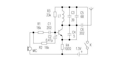
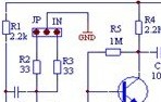
R1 in the circuit diagram of the enhanced wireless microphone is the bias resistance of the microphone MIC, generally selected in 2K-5.6K. R4 is the collector resistance. Give here ...

Published on 2011-12-21 10:48 • 3939 views
Circuit diagram of enhanced wireless microphone
Realization of wireless microphone circuit

This article introduces in detail more than a few representative low-power transmitters in the 88 ~ 108MHz FM broadcast range that are easy to make in amateur situations ...

Posted at 2011-11-22 15:29 • 5745 times read
Realization of wireless microphone circuit
1.5V wireless microphone

The microphone works with a single tube, and the working voltage only needs 1.5V. The frequency is tuned in the FM band of 88 ~ 108MHz, and the ordinary FM radio is used ...

Posted at 2011-10-08 14:31 • 2304 times read
1.5V wireless microphone
Practical test method of wireless microphone

Recently, some film and television sound workers have conducted detailed practical tests on several wireless microphones commonly used in daily work. The pickup of wireless microphone not only involves the distance ...

Published on 2011-02-14 11:42 • 3002 views
Practical test method of wireless microphone
Wireless microphone production circuit diagram

If your recorder has FM reception band, you may wish to make a wireless microphone yourself, which can add a lot of fun to your life.

Published on 2010-11-25 12:27 • 4291 times read
Wireless microphone production circuit diagram
Simple wireless microphone circuit diagram

Posted at 2010-08-25 22:21 • 2139 views
Simple wireless microphone circuit diagram
High-fidelity wireless microphone circuit diagram

The frequency changes. When assembling, the lead of the component should be soldered as short as possible.

Posted at 2010-08-25 21:59 • 824 views
High-fidelity wireless microphone circuit diagram
Circuit diagram of wireless microphone lever pointer

The wireless microphone rod pointer introduced in this article combines the FM wireless microphone and the portable rod pointer, and cleverly uses the metal part of the pointer as a word.

Posted at 2010-08-25 21:51 • 421 views
Circuit diagram of wireless microphone lever pointer
Manufacture of several wireless microphone circuits

The production of several wireless microphone circuits This article introduces in detail the representative ones that are easy to make successfully in amateur situations ...

Posted on 2009-12-24 09:07 • 2942 views
Manufacture of several wireless microphone circuits
Principle and circuit of KMW-306 channel wireless microphone

The principle and circuit of KMW-306 channel wireless microphone KMW-306 wireless microphone is a cost-effective electroacoustic used in karaoke and other dance halls ...

Posted at 2009-12-22 12:34 • 2099 views
Principle and circuit of KMW-306 channel wireless microphone
Production of wireless microphone

The principle of wireless microphone production: The electronic component microphone (microphone) on the circuit board first turns the natural sound signal into an audio electrical signal, which ...

Posted at 2009-12-22 11:02 • 7270 views
Production of wireless microphone
Making wireless microphone and circuit with NAND gate circuit

The use of NAND gates to make wireless microphones and circuit wireless microphones can be seen everywhere on the market, but without exception, all use LC oscillators or quartz crystals ...

Posted at 2009-12-20 09:53 • 500 views
Making wireless microphone and circuit with NAND gate circuit
Wireless microphone circuit made by NAND circuit

The wireless microphone circuit made by the NAND gate circuit is available everywhere on the market, but the circuit is made of lc oscillator or quartz crystal oscillator circuit ...

Published on 2009-11-26 08:20 • 593 times read
Wireless microphone circuit made by NAND circuit
How to choose a wireless microphone

How to choose a wireless microphone Overview Due to the progress of today's radio communication technology, the quality and function of wireless microphone products have been relatively improved ...

Posted at 2009-10-22 21:13 • 2350 views
How to choose a wireless microphone
High-performance dual-band wireless microphone receiving circuit diagram

High-performance dual-band wireless microphone receiving circuit diagram

Published on 2009-10-20 11:34 • 1759 views
High-performance dual-band wireless microphone receiving circuit diagram
Circuit diagram of amplitude modulation wireless microphone

Circuit diagram of amplitude modulation wireless microphone

Published on 2009-04-14 09:43 • 1067 views
Circuit diagram of amplitude modulation wireless microphone
Make signal generator and wireless microphone with UPC1651

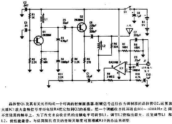
The circuit is shown in the figure, IC1, C1 form a low-frequency oscillator around 400HZ; IC2 ...

Posted on 2006-04-17 19:11 • 754 views
Make signal generator and wireless microphone with UPC1651
FM wireless microphone

Published on 2006-04-16 19:22 • 2823 times read
FM wireless microphone
I made SMD FM wireless microphone

Posted at 2006-04-16 19:21 • 464 times read
I made SMD FM wireless microphone
[Photo] High-sensitivity wireless sounding device

Posted on 2006-04-15 21:00 • 576 views
[Photo] High-sensitivity wireless sounding device
[Photo] Single tube wireless microphone

The circuit shown in Figure 1 can transmit audio signals to remote locations in a frequency-modulated (FM) manner.

Published on 2006-04-15 20:58 • 515 views
[Photo] Single tube wireless microphone
[Photo] upc1651 FM wireless microphone

Published on 2006-04-15 20:58 • 1065 times read
[Photo] upc1651 FM wireless microphone
[Photo] 9018 wireless microphone

The wireless microphone circuit has a reasonable design, beautiful and elegant shape, long sound transmission distance, long service life, long ...

Published on 2006-04-15 20:45 • 890 views
[Photo] 9018 wireless microphone
[Photo] High-sensitivity wireless probe

The device introduced in this article can be used to listen to the weak sound of indoor or outdoor, as long as needed ...

Published on 2006-04-15 20:45 • 335 views
[Photo] High-sensitivity wireless probe
[Photo] Wireless microphone

A few days ago, the price of a wireless microphone on the market was between 10 and 20 yuan. The microphone is adjusted ...

Published on 2006-04-15 20:45 • 740 views
[Photo] Wireless microphone
[Photo] FM wireless microphone

The circuit is shown in the figure. This circuit uses Japanese NE ...

Published on 2006-04-15 20:44 • 328 times read
[Photo] FM wireless microphone
[Photo] Micro FM wireless microphone

Electricity

Posted at 2006-04-15 20:43 • 465 times read
[Photo] Micro FM wireless microphone
var check_allow = "/d/Api/iscantalk.html"; var add_url = '/ d / article / write /'; function CheckLogin () {now_uid = ''; var ElecfansApi_checklogin = '/ webapi / passport / checklogin'; var logout_url = "{: U ('Login / logout')}"; var logout_url = 'http://bbs.elecfans.com/member.php?mod=logging&action=logout&refer=front'; $ .get (ElecfansApi_checklogin, function (data, textStatus) {if (data! = "") {EchoLoginInfo (data); CheckEmailInfo (data); data = $ .parseJSON (data); now_uid = data.uid; / * var login_content = 'write an article
'+ data.username +'
Quit '; * / var login_content =' write an article
'+ data.username +'
Set exit '; $ (' # login_area '). Html (login_content); var win_width = $ (window) .width (); if (win_width> 1000) {$ ("# mine"). MouseDelay (200) .hover (function () {$ ("# mymenu"). show ();}, function () {$ ("# mymenu"). hide ();});}} else {var content = 'Login Registration'; $ ('# login_area'). html (content); $ (". special-login"). click (function (e) {$ .tActivityLogin (); return false;});}});} $ (function () {// comment ------------------------------- var comment = $ ("# comment"); var comment_input = $ ("# comContent"); // Submit comment click event interaction $ ("# comSubmit2"). on ('click', function () {var content = comment_input.text (); // Empty input box comment_input. html (""). focus (); // Submit data to server $ .ajax ({url: '/plus/arcComment.php', data: {aid: $ ("# webID"). val (), dopost : 'apiPubComment', content: content}, type: 'post', dataType: 'json', success: function (data) {// Data format returned: if (data.status == "successed") {// Build temporary comment DOM var dom = ''; dom + = '
'; dom + =' '; dom + ='
'; dom + ='

'+ data.data.username +' '; dom + ='

'; dom + =' '+ content +' '; dom + =' '; dom + =' just now '; dom + =' '; dom + =' '; // insert a temporary comment to the list $ ("# comment ") .append (dom);} if (data.status ==" failed ") {// alert (data.msg); layer.msg (data.msg);}}}); return false;}); (function () {/ * * Insert single sign-on JS * / var setHost = 'https://passport.elecfans.com'; // Set domain name var script = document.createElement ('script'); script.type = 'text / javascript'; script.src = setHost + '/public/pc/js/t.passport.js'; script.setAttribute ("id", "sso_script"); script.setAttribute ("data-ssoSite", setHost); script.setAttribute ("data-ssoReferer", encodeURIComponent (location.href)); script.setAttribute ("data-ssoSiteid", "11"); var body = document.getElementsByTagName ("body"). item ( 0); body.appendChild (script);}) () / * * It is recommended to modify the style of the article without a picture * * / $ (". Article .thumb"). Each (function () {if ($ (this). find ('img'). attr ('src') == "") {$ (this) .find ('img'). remove (); $ (this) .parent (). css ('padding-left ',' 0px ');}}); / * Baidu share * / window._bd_share_config = {common: {bdText: '', // Custom share content bdDesc: '', // Custom share summary bdUrl: window.location.href, // Custom share URL address bdPic: ''} , share: [{"bdSize": 60, "bdCustomStyle": true}]} with (document) 0 [(getElementsByTagName ('head') [0] || body) .appendChild (createElement ('script')). src = 'http://bdimg.share.baidu.com/static/api/js/share.js?cdnversion=' + ~ (-new Date () / 36e5)]; var add_url = '/ d / article / write / '; // var check_allow = "{: U (' Api / iscantalk ')}"; var check_allow = "/ d / api / iscantalk"; var click_items_length = $ ('. art_click_count '). length; if ( click_items_length> 0) {var id_str = ''; $ ('. art_click_count'). each (function () {id_str + = $ (this) .attr ('data-id') + ',';}) // var url = "{: U ('Api / getclickbyids')}"; var url = "/ d / api / getclickbyids"; var id_data = 'id_str =' + id_str; $ .ajax ({url: url, data: id_data, type: 'post', dataType: 'json', success: function (re) {if (re.list.length> = 1) {var list = re.list; for (var i in list) {var t emp_id = list [i] ['id']; var temp_span = $ (". art_click_count [data-id =" + temp_id + "]") temp_span.html (list [i] ['click']);}} }})} $ ("# comContent"). click (function () {if (now_uid == '') {$ .tActivityLogin (); return false;}}) $ (function () {var follow_wrap = $ ( ".author-collect"); var now_uid = "{$ _super ['uid']}"; var face_src = "{$ _super ['uface']}"; var getFollowNum = $ (". followNum strong"). html (); // Follow $ (window) .on ('click', '.author-collect', function () {if (now_uid == '') {$ .tActivityLogin (); return false;} if ( $ (this) .attr ('id') == 'follow') {$ .post ('/ d / user / follow', {tuid: article_user_id}, function (data) {// Data format returned: if (data.status == "successed") {$ (". followNum strong"). html (++ getFollowNum); follow_wrap.html ('followed'). attr ('id', 'cancelFollow'). css ( 'background', '# 999'); var follow_user = ' '; $ (' # follow_list '). append (follow_user);} if (data.status == "failed") {alert (data.msg);}});} else {// Unfollow if ($ ( this) .attr ('id') == 'cancelFollow') {$ .post ('/ d / user / cancelFollow', {tuid: article_user_id}, function (data) {// Data format returned: if (data .status == "successed") {follow_wrap.html ('Follow'). attr ('id', 'follow'). css ('background', '# f90'); $ (". followNum strong"). html (-getFollowNum); $ ('# follow_list .face'). each (function () {var target_uid = $ (this) .attr ('data-uid'); if (target_uid == now_uid) {$ ( this) .remove ();}})} if (data.status == "failed") {alert (data.msg);}}); return false;}}});});}); / * var myface = "{$ _super ['uid'] | avatar}"; var myname = "{$ _super ['username']}"; var article_id = {$ article ['id']}; var article_user_id = {$ article ['mid']}; // Article author ID $ (function () {<notempty name = "clearnum"> // Reduce the number of reminders var count = parseInt ($ ("# noticeCount"). html ()); count = count-{$ clearnum}; $ ("# noticeCount"). html (count); if ( count

Same as the led par20,PAR16 7w DIM led spot light (sometimes used as an interface, called MR16 or GU5.3) is a kind from a number of manufacturers to develop standard halogen reflector lamps. Today Par16 7W Dim Led Spot Light type LED lamp can also be seen.

PAR16 7w DIM led Spot Light are often used in place of standard compact fluorescent or incandescent bulb applications, including residential lighting and retail lighting.

PAR16 7w DIM led spot light
PAR16 7w DIM led spot light was originally designed for slide projectors.
They are suitable for a variety of applications, require a low to moderate-intensity directional lighting, such as track lighting, recessed ceiling lights, table lamps, chandeliers, lamps, landscape lighting, retail display lighting and bicycle headlights.
Folding properties
PAR16 7w DIM led spot light is a name number, where "MR" represent multiple reflector (Multifaceted Reflector). 16 is the length of the diameter of the representative of the former, the number of unit length of multiples, the provisions of 8 units of 1 inch. In MR16 example, the first diameter is 16 units long, 2 inches in diameter before that 2x2.54cm = 5.08cm, diameter of about 5 cm long.

PAR16 7w DIM led spot light

Glass lamp cup, high long life, reliable, halogen bulb brightness, cheap.
PAR16 7w DIM led spot light fatal flaw is: large power consumption, heat lamp great.
There cartridge Friends (flashlight enthusiast) because of cheap, high brightness, good floodlight, which was converted into a flashlight, good results.
Currently such a well-known manufacturer of light cup of GE common NVC, Philips, Osram.


Mingxue Optoelectronics Co.,Ltd. has apply the I S O 9 0 0 1: 2 0 0 8 international quality management system certificate, For PAR16 7w DIM led spot light we apply the CE, RoHS and SAA certificate for our led lighting product.

PAR16 7w DIM led spot light

PAR16 7w DIM led spot light

PAR16 7w DIM led spot light

Par16 7W Dim,White Par16 7W Dim,Energy Saving Par16 7W Dim,Elt Par16 7W Dim

Shenzhen Mingxue Optoelectronics CO.,Ltd , https://www.led-lamp-china.com