Design Flow and Simulation of RF Junction Circulator
Keywords: ferrite, microwave, radio frequency circulator Abstract: The object of this paper is to use a ferrite circulator with a double Y junction in the center of the base station. At the same time, by combining the field theory and the road theory of the junction circulator, this paper derives some general design formulas, gives a concise design process, and gives the simulation results in combination with computer-aided design, which has a certain guiding significance for the general designer. .
1 Introduction Ferrite is a special magnetic material with gyromagnetic properties in the microwave frequency band. Because he has a series of non-reciprocal characteristics, he can use him to construct a series of microwave non-reciprocal devices such as circulators. Microwave circulators have become one of the indispensable key devices in the fields of information communication, electronic countermeasures, aerospace and other fields. Nowadays, the application of microwave circulators is rapidly expanding into the fields of civil communication, energy technology, industry, agriculture and medicine.
The circulator has a one-way transmission characteristic, the incident signal can pass smoothly, and the reflected signal cannot be passed because it is absorbed by the absorption resistor.
Its working principle is to use the resonance effect generated when the central structure satisfies a certain relationship between the RF field and the applied bias magnetic field, thereby obtaining the circular effect. Currently, circulators generally use disk junction, Y-junction, double Y-junction, and triangular junction center resonant conductors. The object of this paper is to use a ferrite circulator with a double Y junction in the center conductor of the base station.
According to the design, the simulation results satisfy the isolation greater than 26 dB, the insertion loss less than 0.3 dB, and the return loss greater than
26 dB, the voltage standing wave ratio is less than 1.14, the outer radius of the center conductor is about 5 mm, achieving both high performance and miniaturization,
Basically meet the requirements of almost all GSM base stations for circulators. At the same time, by combining the field theory and the road theory of the junction circulator, this paper derives some general design formulas, gives a concise design process, and gives the simulation results in combination with computer-aided design, which has a certain guiding significance for the general designer. .
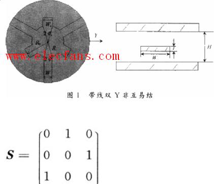
2 Design process Figure 1 is a schematic diagram of the structure of a double Y-band junction. The radius of the metal conductor disc is R, the length of the small Y arm is R0, the coupling angle is φs, the width is Ws, the electrical length is θs, the width of the large Y arm is W, the coupling angle is φ, the thickness of the ferrite is H, the thickness of the metal conductor Is t. The core of the circulator is a ferrite non-reciprocal junction with a constant magnetic field applied. The center conductor can generally be in various shapes such as disc, Y, double Y or triangle. Through network theory analysis, it can be proved that a matched lossless symmetrical three-terminal junction is a circulator, which is expressed by the scattering matrix as:
If this non-reciprocal junction is lossless, the disk double Y is derived from the disk junction wave equation by plus and minus and in-phase eigen excitation
The in-phase of the junction and the eigenvalues ​​of positive and negative excitation impedance:
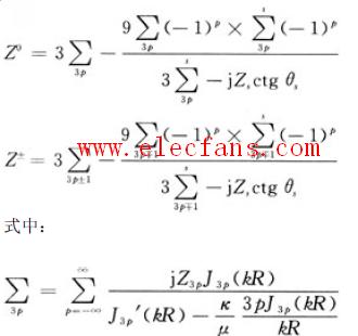 Z0 and Z ± are pure imaginary numbers. If the distribution of the normalized value on the impedance pie chart and the phase angle difference between the corresponding S eigenvalues ​​are 120o, then this non-reciprocal junction is circular. Here we can take the normalized admittance eigenvalues ​​for discussion, and it must have:
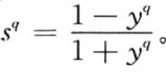
Here yq represents the eigenvalue of the normalized admittance, and the eigenvalue of the normalized scattering matrix corresponding to sq, so that the non-reciprocal scattering parameter can be expressed by its eigenvalue
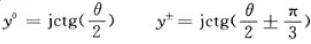
The above circular conditions are common to all non-reciprocal junctions, and the circular performance parameters are ideal parameters that satisfy the circular conditions. Then, by deriving the above formula, the circular conditions of the double Y junction of the disk under the fundamental mode can be obtained, which is obtained under the normalization of the junction impedance. Under the joint action of the two fundamental modes, the first and second circular conditions can be known :
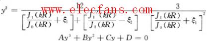 In the formula:

Then get the value of y through the looping condition to derive the junction impedance 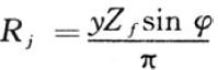 . The concept of the junction resistance Rj of the non-reciprocal disk junction is that if all three terminals of the non-reciprocal junction are connected to the source or load impedance with the impedance Rj, then the non-reciprocal junction is circular. Where Zf is the characteristic impedance of the ferrite stripline, and φ is the coupling angle between the Y arm and the disk.
 By defining the working frequency of the circulator by the above formula, selecting the ferrite with the appropriate saturation magnetic field strength, and then determining the external bias magnetic field, the normalized saturation magnetic moment and the normalized internal field magnetic parameters are obtained. Then a set of parameters (y; K / μ; kR) can be obtained by deducing the looping conditions of the double Y junction. Therefore, if the device is designed according to this set of parameters, it must be an ideal circulator,
So the design of the circulator is to carefully study this set of parameters, understand how they are related to each other, and how to restrict each other,
In order to choose reasonably to obtain better performance.
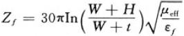
The y parameter is the normalized admittance parameter. As can be seen from the above formula, it mainly depends on the structural parameters W, H, and
t, φ, ξ1, ξ2, ferrite dielectric constant εf and effective tensor permeability μeff. The circulator structure parameters and εf are usually determined in advance, so y mainly depends on the selection of the ferrite magnetic parameter μeff.
The k / μ parameter is the diagonal component of the tensor permeability divided by the diagonal component, which is also the magnetic parameter of the ferrite.
kR is the magnitude of the Bessel function, where R is the radius of the ferrite and k is the wavenumber 
The magnetic parameters μeff, μ, k depend on the normalized magnetic moment of the ferrite and the normalized internal magnetic field. The magnetic parameters k, μ, μeff in the case of saturation magnetization and no loss can be obtained by the following formula: 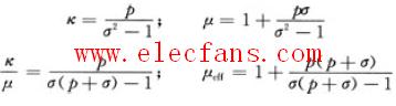
In the formula, p and σ respectively represent the normalized saturation magnetic moment and the normalized inner field: 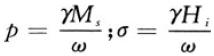
In the formula, Ms is the ferrite saturation magnetization; Hi is the size of the applied bias magnetic field.
The following analyzes the main design process:
First determine kR, that is, choose the radius R and the magnetic field operating point, determine μeff, k / μ, and get kR. Then calculate y, which is known as kR, and calculate y from the first loop condition. The junction resistance Rj usually obtained by y is not able to connect with the transmission line of the circulator. Because the characteristic impedance of the general transmission line is 50 Ω, the circulator needs to be matched to connect people, so you must add a matching network or change the structural parameters, especially H or φ, ξ1, ξ2, etc., to make the system match.
Then calculate k / μ, that is, kR and y are known, and k / μ is calculated from the second loop condition. If the calculation result is consistent with the previous p and σ
If the determined value of k / μ, the design is successful; otherwise, kR needs to be re-determined, and the loop calculation is performed until the conditions are met.
It can be calculated by Matlab, and the error is usually acceptable within 0.05.
It can be seen from the above design flow that the key to the design of the junction circulator is to select R, p, and σ, so a reasonable range needs to be given. For example, for low-field devices, in order to avoid zero field loss, p is usually selected between 0.4 and 0.7, and the applied magnetic field should saturate the material, that is, σ = 0, the bias magnetic field is 0. Available k / μ = p; μeff = 1-P2. As for the selection of R, if the device miniaturization is considered, it should be as small as possible; on the contrary, if it is a high-power application, it must be larger. Generally, the value of kR is determined between 0.8 and 1.8, and for high-field devices, σ> 1 and p> 1 must be made, and it should not be too large, the approximate range is
1.5 <σ <2, 1
3 Simulation results and analysis The frequency range studied in this paper is 925 ~ 960 MHz at the GSM receiver, which belongs to the low end of the microwave frequency band, so the bias magnetic field required by the circulator is selected to be higher than the ferrite resonance field. In the high field operation, the device size can be as small as possible, but also requires a higher magnetization saturation magnetization material and a higher bias magnetic field. The simulation uses a saturation magnetization of 1 800 Gauss
(Gauss), a ferrite material with a line width △ H of 40 Oe and a loss tangent tan δ = O.005.
The parameters calculated with reference to the above design flow are: R = 4.0 mm, R0 = 1O mm, W = 3.1 mm, φs = 36, φ = 22,
H = 2.2l mm, t = 0.2 mm, k / μ = 0.52, normalized admittance y = 4.53, junction impedance Rj = 14.6, and the error of the loop condition is 0.003.
Use HFSS electromagnetic field simulation software on the computer for 3D modeling and simulation, and set the appropriate boundary conditions and excitation sources. The simulation scans the operating frequency F and the internal bias magnetic field strength Hi, and compares and analyzes the performance parameters.
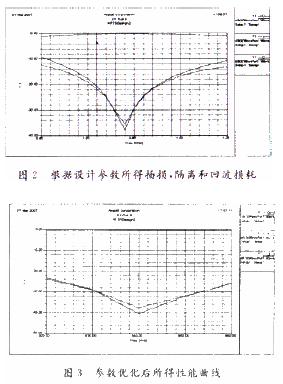
Because the matching part uses two-level non-incremental matching, the calculated results are not optimal in simulation, as shown in Figure 2. Here, the optimization function OPTImetrics module that comes with HFSS is used to create the structure parameters of the circulator as variables.
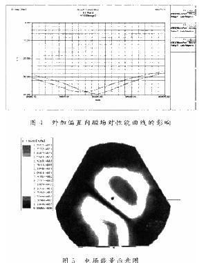
The COST function is optimized for the objective function, and the loop performance is greatly improved, as shown in Figure 3. In addition, by comparing the size of the internal magnetic field, the analysis shows that under the same external dimensions, the size of the internal magnetic field has a great influence on the performance of the circulator, especially the curve is steeper near the resonance frequency, see Figure 4. Choose the best inner field close to 39 at a resonance frequency of 940 MHz
000 (A / m). Through repeated fine-tuning of the internal magnetic field, the final performance curve is that the isolation in the band is greater than 24 dB, the insertion loss is less than 0.3 dB, the return loss is greater than 26 dB, and the voltage standing wave ratio (VSWR) is less than 1.12. The isolation at the resonance point is 41 dB,
The insertion loss is 0.22 dB, the return loss is 38 dB, and the voltage standing wave ratio (VSWR) is 1.03, which fully meets the actual high-performance requirements of GSM. From the electric field energy diagram, it can be clearly seen that the energy transmission of ports 1 to 3, while port 2 has almost no energy and is isolated, see Figure 5. The simulation results prove that the parameter values ​​obtained according to the design method of this article are very close to the best performance index,
Verifies that the design flow and simulation of this article are feasible.
For the research and design of ferrite circulators with double Y junction circulators, their own design schemes are given according to the circulatory conditions, and the design results are tested by simulation software, which proves the correctness, feasibility and practical application value of the design . It has a strong guiding significance for the design of general junction circulators, which is in line with the development trend of modern higher performance advantages and miniaturization characteristics.
Wall plug adapter with interchangeable plugs, AC Switching Adapter with detachable AC plug, universal adapter, switching interchangeable power adapter, interchangeable power supply,16V Detachable Plug Power Adapter with 6 different plug types (CN, USA, EU, KR,AU and UK).
16V detachable plug power adapter for tablet, bluetooth speaker, massage chair, humidifier, juice extractor, coffee machine, small household appliance, fingerprint scanner, CCTV camera-etc
With these 6 interchangeable plug -- CN,KR,US,EU,AU,UK plug, you can only take one 16V wall plug in power adapter with you when you traveling among these 6 countries.
We can also make it with more plugs if you tell us your specific requirement.

16V Detachable Plug Power Adapter
16V Detachable Plug Power Adapter,Interchangeable Detachable Power Adapter,Detachable Power Adapter
Shenzhen Juyuanhai Electronic Co., Ltd. , https://www.powersupplycn.com