Design and Implementation of OFDM Synchronization System Based on IEEE 802.1la
The fourth-generation mobile communication will provide data transmission rates of up to 100 Mb / s or even higher, and can meet the high-quality multimedia services from voice expansion to large amounts of information such as data, images, and video. With the rapid development of wireless communication services, in order to improve the utilization rate of frequency bands under the situation that the available frequency bands are becoming increasingly tight. Orthogonal frequency division multiplexing (Orthogonal Frequency Division MulTIplexing. OFDM) has become the core technology of the fourth generation mobile communication system. The basic idea is: divide the channel into several orthogonal sub-channels, convert high-speed data signals into parallel low-speed sub-data streams, and modulate each sub-channel for transmission. Each sub-channel maintains orthogonality, and the spectrums overlap with each other. Compared with single-carrier modulation, the spectrum utilization is improved. However, OFDM systems are more sensitive to timing errors and frequency offsets than single-carrier modulation, and their synchronization accuracy requirements are higher than single-carrier modulation. Higher, the synchronization deviation will cause serious ISI (Inter Symbol Interference, Inter-Code Interference) and ICI (Inter Carrier Inteference, Inter-Carrier Interference) in the OFDM system. In addition, due to the waveform of the OFDM signal, many synchronization algorithms designed for single carrier systems cannot be used. Therefore, the study of synchronization system is of great significance to the realization of OFDM broadband data communication system.
The original meaning briefly introduces the OFDM system structure, analyzes the effect of synchronization on the OFDM system, designs an OFDM synchronization system scheme based on the IEEE 802.1la protocol, and focuses on frame synchronization, symbol synchronization and carrier synchronization and tracking The key technology, and finally implemented the entire program using FPGA.
1 OFDM system structure and synchronization deviation affect the performance of the system
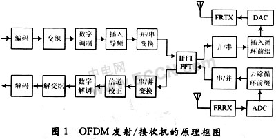
1.1 System structure of OFDM
The system structure of OFDM is shown in Figure 1.
 |
1.2 The influence of synchronization deviation on the performance of the system
The OFDM baseband signal expression is as follows:
![]()
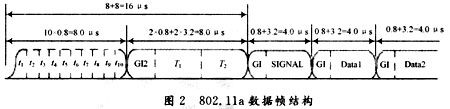
Where: N is the number of subcarriers (N = 64), ak and m are the modulation coefficients of each subcarrier, T is the duration of OFDM symbol 4 μs (including cyclic prefix 0.8 μs and FFT symbol width 3.2 μs), T0 is an OFDM The period length of the symbol is 3.2 μs (excluding the cycle length), and f0 = 1 / T0.

It can be seen that when the sending and receiving ends are not synchronized, the system performance will be affected from the following three aspects:
(1) Generate a phase rotation for each sub-channel of the received signal;
(2) Reduce the orthogonality of each sub-channel of the received signal and increase the noise of each sub-channel;
(3) Reduce the signal power of each sub-channel of the received signal.
Therefore, the unsynchronization of the system will greatly affect the signal recovery, so the receiver must adopt an effective synchronization method. Under normal circumstances, the sampling clock offset is negligible. The following is the scheme design of the system synchronization part.
2 Synchronization scheme design
There are two basic methods for common synchronization: one is non-data-aided (NonData Aided, NDA) synchronization; the other synchronization method is data-aided (DataAided, DA) synchronization. The synchronization time of the non-data-assisted mode is relatively long, and the communication system of the broadcast mode does not have high requirements on the synchronization time. This mode can be used, and for the wireless broadband communication of the burst mode, a fast synchronization establishment time is required. Data-assisted synchronization is generally used. Considering several factors such as system resources, synchronization time, and implementation complexity, this system uses data-based synchronization based on long and short code training sequences and auxiliary pilots.
 |
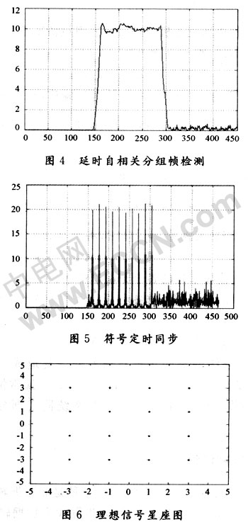
In general communication systems, the frame synchronization process is often completed after carrier synchronization and symbol timing synchronization. But for the IEEE 802.11a system, the nature of its burst communication determines that its frame synchronization needs to be completed before carrier synchronization and symbol synchronization, that is, frame synchronization is established in the presence of carrier frequency offset and symbol timing offset. Commonly used frame detection methods include energy detection method and double sliding window group detection method. When performing frame detection, frequency synchronization has not yet been performed, and the received complex baseband signal may have a large frequency deviation. Therefore, it is necessary to select an algorithm that is less affected by the frequency deviation. In this paper, the delay autocorrelation algorithm based on Schimdl & Cox is selected, and on this basis, the filter protection count is introduced to reduce the probability of false detection.
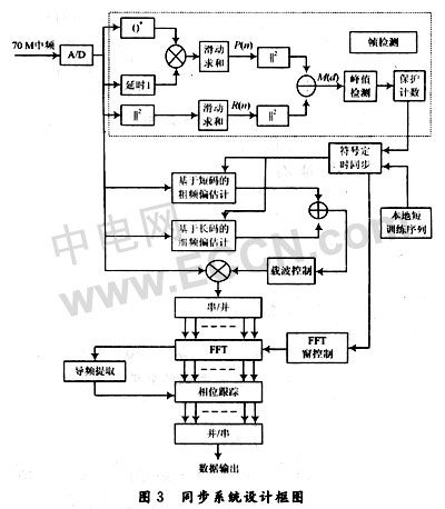 |
P (d) is the cross-correlation value of the received signal and the received signal delay, D = 16, which represents the period of the short training sequence, R (d) represents the energy of the corresponding received signal, which is used to normalize the decision statistics, The sample value of the complex baseband signal input by rd. When the value of M (d) jumps rapidly to the maximum value, it indicates that the data frame signal has arrived.
2.2 Symbol synchronization
Accurate symbol synchronization is usually based on correlation operations in the time or frequency domain. Warner and Bingham used the correlation characteristics of the pilot signal in the frequency domain, and Couasnon used the redundant information contained in the cyclic prefix. Considering the difference between burst data and broadcast data such as DVB, the short training sequence has the characteristics of sharp autocorrelation peaks, and the sharp correlation peaks of the received signal and the local training sequence signal are used to achieve accurate symbol synchronization. In the formula, Sd is the local short training sequence complex signal, and rd is the received baseband complex signal. According to the value of M '(d), the precise synchronization of the symbols is completed.
![]()
2.3 Carrier synchronization and tracking
OFDM systems are very sensitive to carrier frequency offsets. Smaller carrier frequency offsets will cause ICI between adjacent subcarriers and destroy the orthogonality between subcarriers. Generally, a 1% carrier frequency offset will cause serious system problems. Impact. After the same two parts in the training sequence are transmitted through the channel, they will have a phase offset due to the deviation of the carrier frequency. By calculating the phase offset value, you can get an estimate of the frequency offset. The estimation accuracy is directly related to the period of the repeated training sequence. Here, the repeated short training sequence is used to complete the coarse frequency estimation, and the repeated long training sequence is used to complete the fine frequency estimation. 
D is the delay between the same samples of two repeated symbols. D = 16 in the short training sequence and D = 64 in the long training sequence. Therefore, it can be seen from the above formula that the frequency estimation ranges of the short training sequence and the long training sequence are 625 kHz and 156.25 kHz, respectively. The frequency estimation method combined with long and short training sequences not only solves the problem of wide capture range, but also improves the capture accuracy.
Frequency offset estimation is not a complete process. After the time-domain frequency offset estimation is corrected, there is still some residual frequency offset error (within 4kHz). Due to the increase in the duration of the OFDM frame, the residual frequency offset error will cause a phase offset It keeps increasing, so as the phase deviation increases, it will cause the rotation of the constellation diagram, and even cause the demodulation failure.
Since each symbol in 802.11a has 4 symmetric pilots in the frequency domain (respectively on -21, -7, +7 and +21 subcarriers). Therefore, it is possible to extract 4 pilots in the frequency domain after FFT, and then according to the average value of the phase shift of the 4 pilots: ![]()
Correct and track the phase rotation caused by the residual frequency offset.
3 System simulation
Assuming that the frequency stability of the crystal oscillators of both the sending and receiving sides is 20 ppm (the IEEE 802.11a stipulates that the maximum deviation of the sending and receiving carrier frequencies is ± 20 ppm), the carrier frequency is 5 GHz. In the worst case, the frequency error at the receiving end is 40 ppm, that is, 5 × 109 × 40 × 10-6 = 200 kHz.
System simulation environment: Rayleigh channel, signal-to-noise ratio is 20dB, adopts 16QAM modulation mode, input artificial frequency deviation is 300kHz, 200 OFDM symbols.
According to the designed synchronization scheme, the simulation diagram is shown in Figure 4 to Figure 8.
 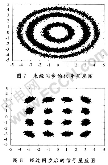 |
By observing the constellation of the 16QAM received signal, it can be clearly seen that whether or not synchronization plays a decisive role in signal recovery, the synchronization system solution can correctly recover the original signal under the condition of low noise ratio.
4 FPGA implementation
The realization of the entire synchronization system is completed in the baseband digital domain. We use the Cyclone II FPGA introduced by ALTERA and design in the Quartus II 5.1 development environment using VHD language. The SignalTapâ…¡ logic analyzer in Quartusâ…¡ is used in the design to observe the synchronization results.
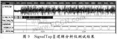 |
The first line is the 70MHz intermediate frequency A / D sampling signal input; the second line is the judgment information of the frame detection; the third line is the frame synchronization signal to the detection flag. In order to prevent frame false detection, a protection count is added, so the frame detection signal is relative to the data signal There is a certain delay in the arrival of the; the fourth line indicates the position of the long code symbol; the fifth line provides the window control signal to the FFT. The high level segment represents the data segment (3.2μs), and the low level interval is the cyclic prefix (0.8μs) ); The last line is the estimated control value of the frequency offset (estimated value with reference to 80MHz), which is used to feed the NCO to correct the local carrier. The middle section is the coarse frequency offset estimation value of the short training sequence, followed by the long and short The two training sequences estimate the final value of the frequency offset. It can be seen that the frequency offset correction value ![]()
It is basically consistent with the input that the frequency offset is 300kHz, and the phase rotation caused by the remaining frequency offset can be corrected with the pilot frequency in the frequency domain.
5 Conclusion
Synchronization is one of the key technical issues of FDM systems. Based on the IEEE802.11a protocol, around the synchronization of burst OFDM systems, a comprehensive consideration is given to frame synchronization, symbol timing synchronization, and carrier synchronization and tracking. The system solution can quickly achieve system synchronization under the condition of large frequency offset and low signal-to-noise ratio.
FIRSTPOWER offers a full assortment of back-up batteries delivering a multitude of applications as Network Power & Reserve Power. Applications include telecommunications, computers, security systems, emergency lighting, power plant systems, medical, alternative energy, railway crossings, and various forms of military equipment used in mission critical environments.
Network Power,Reserve Battery,7 Days Power Reserve Battery,Reserve Power Battery
Firstpower Tech. Co., Ltd. , https://www.firstpowersales.com