The CAN protocol is a widely used communication standard in automotive and industrial applications. It has been standardized by the International Organization for Standardization (ISO), with two main versions: ISO 11898 and ISO 11519-2. Both standards define the data link layer in the same way, but they differ significantly in their physical layer specifications.
ISO 11898 is designed for high-speed CAN communication, typically operating at speeds up to 1 Mbps. Originally, this standard included both the data link and physical layers. However, it was later split into two parts: ISO 11898-1, which covers only the data link layer, and ISO 11898-2, which focuses on the physical layer. This division allows for more flexible and specialized implementation of CAN systems.
On the other hand, ISO 11519-2 is intended for low-speed CAN communication, with maximum speeds of up to 125 kbps. It is often used in applications where cost and simplicity are key factors, such as in certain vehicle control systems or industrial automation setups.
The differences between ISO 11898 and ISO 11519-2 can be seen in various aspects of the physical layer. These include the signaling method, voltage levels, and termination requirements. For example, ISO 11898 uses a differential signaling approach with specific voltage thresholds for dominant and recessive states, while ISO 11519-2 may have different tolerances and configurations.
In terms of bus topology, a typical CAN network consists of two wires—CAN_High and CAN_Low. The potential difference between these two lines determines the bus state. There are two levels: dominant (representing a logical '0') and recessive (representing a logical '1'). When a node transmits a message, it changes the bus level accordingly, allowing all nodes on the network to receive the information.
The physical layer also defines the required termination impedance, which is crucial for signal integrity. Different standards may require different types of transceivers to ensure compatibility and proper operation. For instance, ISO 11898 and ISO 11519-2 each specify their own transceiver ICs that must be used to meet the respective standards.
Beyond ISO, other organizations such as SAE (Society of Automotive Engineers) and NMEA (National Marine Electronics Association) have also contributed to the development and standardization of CAN-based protocols. These standards help define communication methods for different application areas, such as automotive, marine, and industrial systems.
For example, SAE has developed several standards like J1850, which is used in some vehicle networks, while NMEA provides guidelines for marine electronics. Additionally, private companies and research institutions have created proprietary CAN protocols tailored for specific use cases.
Understanding the differences between these standards is essential when designing or implementing a CAN-based system. Factors such as communication speed, bus length, and environmental conditions must be carefully considered to ensure reliable and efficient data transmission.
By selecting the appropriate standard and components, engineers can build robust and scalable CAN networks that meet the needs of modern automotive and industrial applications.

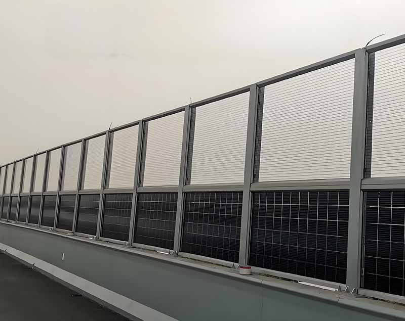
Photovoltaic(PV)noise barriers,also known as"noise barriers with integrated solar panels"or"solar noise barrier,"combine noise reduction infrastructure with renewable energy generation. These systems are increasingly being deployed along highways,railways,and urban areas to mitigate noise pollution while generating clean electricity.

How Photovoltaic Noise Barriers Work
1. Dual Functionality
-Noise Reduction:Acts as a traditional noise barrier,blocking or reflecting sound waves from traffic or industrial sources.
-Solar Power Generation:Solar panels integrated into the barrier convert sunlight into electricity,which can be fed into the grid or used locally.
2. Design Configurations
-Transparent PV Panels:Used where visibility is important(e.g. ,along highways). -Opaque PV Panels:More efficient but block the view.
-Bifacial Solar Panels:Capture sunlight from both sides,increasing efficiency.
-Vertical or Tilted Mounting:Optimized for space constraints and sunlight exposure.
Advantages of Photovoltaic noise barrier
✅Space Efficiency:Uses existing noise barrier infrastructure,avoiding additional land use.
✅Renewable Energy Generation:Contributes to local or grid-based solar power.
✅Noise Pollution Control:Maintains primary function of reducing traffic/industrial noise.
✅Aesthetic&Functional Integration:Can be designed to blend with urban or natural landscapes.
✅Government Incentives:Some regions offer subsidies for solar-integrated infrastructure.
Challenges&Considerations
âš Lower Efficiency:Vertical mounting may reduce solar output compared to optimally tilted panels.
âš Shading&Orientation:Barriers along north-south roads may have uneven sunlight exposure.
âš Maintenance:Cleaning panels on highways/railways can be logistically challenging.
âš Higher Initial Cost:Integration of PV adds to upfront costs,though long-term savings offset this.
Photovoltaic sound barrier,Solar-powered sound barrier,Photovoltaic noise barrier,Solar noise barrier
Hebei Shuobiao New Energy Technology Co., Ltd. , https://www.pvbracketsystem.com