1. Foreword
This article refers to the address: http://
Cars have dramatically changed people's lives with their convenience. With the improvement of living standards, the continuous advancement of automotive technology and the rapid development of the automotive industry, the number of cars has increased dramatically. The resulting energy consumption, environmental degradation and other issues contradict the current world's energy saving and environmental protection trends. How to find a balance in the development of the automotive industry and the sustainable development of the environment has become a major issue facing the automotive industry today. Hybrid vehicles and pure electric vehicles are slowly developing and growing in this situation.
As the main controller of the whole hybrid system, the vehicle controller (HCU) undertakes functions such as energy distribution, torque management and error diagnosis of the entire system. Power battery is one of the main components of hybrid vehicles and pure electric vehicles. Its management and control is also a special key technology in the development of hybrid vehicles.
2. Development of vehicle controller
2.1 vehicle controller (HCU) development mode
The development of Changan Hybrid Vehicle Controller (HCU) adopts the V-type development mode. Mainly can be divided into the following stages:
2.1.1. Functional development phase function
The development phase is mainly used to verify the system design scheme. At this stage, matlabsimulink is used to establish a simple control strategy model, which combines the vehicle model, engine model, motor system model and battery system model. Simulate the fuel consumption and power of the vehicle. If the simulation fuel consumption and power performance at this stage do not meet the design requirements, the system design plan must be modified, and after the fuel consumption and power are achieved, the rapid prototyping stage is entered.
2.1.2. Rapid prototyping stage
The main job of the rapid prototyping phase is functional verification. In the development process, Changan selected Dspace's MicroAutobox as the hardware carrier of the HCU, and used the RTI toolkit to add appropriate input and output interfaces based on the functional development and established control strategy model, and then through the real-time workshop that comes with Matlab. Convert the model to C and download it to MicroAutobox. Then test on the HILI bench, after the logic test is completed, install the Autobox into the car for functional testing.
From the middle of the rapid prototyping phase, we started hardware circuit design, practical software design and so on.
2.1.3 Automatic code generation
In this phase, the first thing to do is to add the control strategy of the rapid prototyping phase to the targetlink interface, and then use targetlink to convert the model into c language code that can run on the target processor.
2.1.4 Hardware-in-the-loop simulation
The hardware in loop phase mainly uses the hardware provided by dspace to perform semi-physical simulation on the ring platform to verify the logic function of the HCU software.
2.1.5 Real vehicle verification phase
At this stage, the software that passes the HIL test is downloaded to the HCU hardware, and then the function of the HCU software is tested for a long time. After the software function test is completed, the data is matched.
2.2 HCU hardware circuit design
The HCU hardware board selects a mature engine control system product, and the main control chip is MC9S12XDP512. The HCU hardware mainly includes the following functions:
Digital signal input and output processing unit: mainly used to process the input and output of digital signals.
Analog signal input processing unit: mainly used to process the relevant temperature signal in the whole vehicle.
Frequency signal input and output processing unit: used to control the safety collision signal and the control of the cooling fan of related components such as batteries.
CAN communication input and output processing unit: mainly used to process communication between controllers of the whole vehicle.
2.3 HCU software design
In the HCU software, a simple real-time system is used to manage tasks. The real-time system belongs to a non-preemptive time system, and each task is executed periodically.
HCU software is divided into three parts: upper layer software, low layer software and interface software. The upper layer software is converted from the model established by MATLAB\SIMULINK, and all control strategies are implemented by the upper layer software. The underlying software is mainly used for signal reception, transmission, and diagnosis, and the calibration protocol function is also implemented by the underlying software. The main functions of the interface layer software are signal processing, reading and writing of EEPROM, FLASH, etc., and fault storage. The data exchange between the underlying software and the interface layer software is mainly implemented by semaphores.
2.4 HCU main functions
2.4.1 Torque distribution
The main function of this function is to distribute the torque of each power component in the vehicle according to the driving intention and manage the remaining battery capacity (SOC) of the power battery.
2.4.2 Fault Detection
The main function of this function is to judge the fault level of the vehicle according to the faults that the vehicle components notify the HCU and the HCU itself through CAN communication.
2.4.3 Offline detection
This function is mainly used for automatic detection during the vehicle's offline process, and detailed inspection of the relevant components of each hybrid power system in the vehicle to ensure the quality of the off-line vehicles.
2.4.4 Powering On and Off Process Processing
The main function of this function is to coordinate the power-on and power-down processes of each hybrid-related component, including the power supply of the motor management system (IPU), battery management system (BCU), pre-charge relay, main relay pull-in and off. Open time and so on.
3. Battery management system design
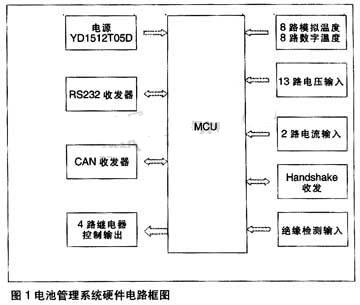
3.1 Battery Management System Hardware Design
The hardware circuit is divided into 9 modules: MCU module, power module, current sensor module, voltage sensor module, CAN transceiver module, R232 transceiver module, relay module, HANDSHAKE module, insulation detection module. (As shown in Figure 1)
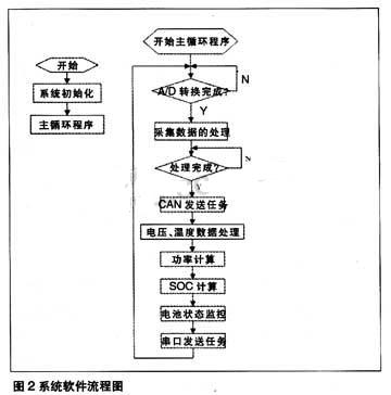
3.2 Battery Management System Software Design
According to the control requirements, the software part of the system consists of 8 tasks, including system initialization, acquisition and processing tasks, CAN transmission tasks, SOC calculation, temperature and voltage data processing, power estimation, battery status monitoring, and serial port transmission. Except for the initialization task, the execution period of each task is 10ms. Among them, the acquisition processing task is the most basic task, and its priority is the highest. The system uses the timer interrupt trigger mode to implement the periodicity of task execution.
The interrupt generated by the timer has two types of underflow interrupt and period interrupt. The cycle interrupt is used to trigger the execution of the task with an interrupt period of 10ms. In the service program of the underflow interrupt, the CAN receiving process including the selection and inquiry mode of the voltage acquisition channel is performed, and the interruption period is 10 ms. In addition to the timer interrupt, the serial interrupt is also set in the software to receive the information sent by the host computer.
In the software implementation task, the initialization task is mainly to configure the register parameters of each module in the DSP, including clock multiplier setting, timer setting, CAN communication parameter setting and serial communication setting. The acquisition processing task is to process the A/D conversion results, including the processing of voltage, current, and temperature sampling results. The CAN transmission task is to report the status information of the battery to the whole vehicle. According to the requirements of the whole vehicle, the transmission period of each information frame is different. In the temperature and voltage data processing tasks, the corresponding values ​​are calculated based on the collected values, and the maximum and minimum values ​​of the module voltage are calculated. The calculation of the SOC and the calculation of the charge and discharge power of the battery constitute an estimate of the energy state of the battery. The serial port sending task is to send information to the display interface of the upper computer to realize real-time display of battery information. The battery status monitoring function includes fault diagnosis and relay control functions.
4. in conclusion
Hybrid is an emerging technology in China, and Changan's goal is to master key core technologies and have independent development capabilities. Among them, many technologies are starting from scratch, there is no precedent in China, and a set of gradually improved development processes must be established. However, Changan chose to face the difficulties, make full use of and integrate the domestic and foreign advantageous resources, and set up an excellent development team to tackle the core technology. In the end, Changan achieved substantial results and successfully developed a hybrid electric vehicle with advanced level in China.
Copper Core Fire Resistant Cable(FR cable) is copper core electrical cables with PVC or XLPE insulation. This cable is suitable for those places with fire resistance requirement. With fire resisting insulator, this cable can ensure to keep normal electrical power on within a certain time if the fire happens. Especially suitable for electric power distribution in fire emergency system such as fire alarm, fire-fighting facility, urgent evacuation.
Product Features
l Light weight & long lifetime
l Reliable and efficient
l Safe and secure
l Easy to implement in the circuits
Using features:
l Rated power-frequency voltage Uo/U: 0.6/1kV
l Max. permissible continuous operating temperature of conductor:
PVC Type: 70℃,
XLPE Type: 90℃
l Max. temperature of conductor during short-circuit(5s maximum duration) shall not exceed:
PVC Type:160℃
XLPE Type:250℃
l The ambient temperature under installation should not below 0℃.


Application
l Steel mills and wind power mills
l EOT Cranes& Ships
l Airport lighting
l Nuclear and thermal power stations
l Electrical and textile machines
l Construction equipments
FAQ
Q: Are you a factory or trading company?
A : We are a manufacturer. We are professional in
developing and producing electrical wires and cables since 2001.
Q: Can I visit your factory?
A :Yes! You are welcome to visit our factory for further detail check.
Our factory is located in Minqing,Fujian.You could choose to fly to Xiamen/Fuzhou International airport. And tell us your flight No. We will arrange to pick you up if you like.
Q: May I buy samples from you?
A: Yes! You are welcome to place sample order to test our superior quality and services.
Q: Can you put my brand name (logo) on these products?
A: Yes! Our factory accepts to print your logo on the products.
Q: May I know the status of my order?
A: Yes .The order information and photos at different production stage of your order will be sent to you and the information will be updated in time.
We are professional manufacturer of electrical fire retardant cables, our products are produced according to IEC testing standard. Welcome to visit our factory.
Copper Core Fire Resistant Power Cable
Copper Core Fire Resistant Power Cable,Fireproof Electrical Cables,Multicore Fire Resistant Electrical Cabels,Fire Resistant Power Cables
Fujian Lien Technology Co.,Ltd , http://www.liencable.com