1 system overall design and working principle
This article refers to the address: http://
One of the main goals of the system is to achieve miniaturization of the system. For this purpose, hardware compression is adopted, and the core chip adopts sz1510 high-performance compression coding chip of Zepax Company. Sz1510 can work in mjpeg, mpeg-1 encoding and video encoding in vcd format. mjpeg encoded image quality is very good, but the code rate is very high, requiring large capacity disk storage, because disk storage requires higher working environment. If the disk storage is used in the airborne environment, the corresponding shock absorption, constant temperature and other protective equipment must be added, resulting in a large increase in volume, while the mpeg-1 coding compression ratio is high, the code rate is relatively low, and the image quality meets the actual needs. And system design requirements, so the system uses mpeg-1 encoding scheme, at the same time, through the use of large-capacity semiconductor memory, greatly reducing the size of the system, improving the system's seismic resistance, reliability, and achieving system miniaturization.
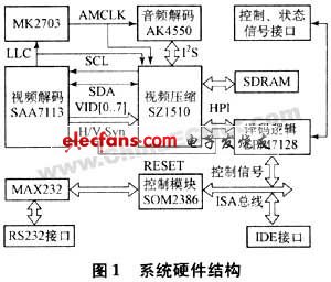
The overall structure of the system is shown in Figure 1. The hardware circuit mainly includes a video and audio decoding unit, a compression coding unit, a decoding logic, and an interface unit.
5 parts of control unit and storage unit.
  
Â
After the system is powered on, som2386 initializes the audio and video encoding module. After the system starts normally, saa7113 decodes the input composite video signal to generate ccir-601 digital video stream, and ak4550 collects the input analog audio signal to generate pcm digital audio stream. It is sent to the compression coding chip sz1510, compressed into the mpeg-1 system stream, and stored in the file format to the electronic hard disk under the control of som2386.
2 hardware design
In order to improve the maintainability of the system and reduce the maintenance cost, the hardware structure of the system adopts a modular design method, and the system is divided into three modules:
a) video and audio decoding and compression coding module: including saa7113, mk2703, ak4550, sz1510, sdram;
b) logical connection, conversion and interface module: including epm7128, max232, rs232 interface, ide interface, control, status signal interface;
c) Control and storage modules: including som2386 and electronic hard drives.
Each module is made into a relatively independent circuit board, and the modules are connected by connectors. If a module in the system fails, it is only necessary to replace the module, and it is not necessary to replace the entire system, which is beneficial to save time and reduce cost.
2.1 Video audio decoding and compression decoding part design
The video decoder uses philips's saa7113, which is a programmable video processing chip that can be programmed and controlled by a simple i2c bus. It has 4 channels of video input, anti-aliasing filtering, automatic clamping and gain control, and multi-standard. Decoding and brightness, contrast and saturation control bring great convenience to the system design. It samples the input pal composite video signal and decodes it to generate 8bit/pixel ccir-601 digital video stream. The space is ycbcr, the sampling is 4:2:2), and is sent to the digital video input interface of the video compression chip sz1510. Its input clock is provided by an active crystal oscillator of 24.576mhz, and the field synchronization signal vs and the line synchronization signal hs are provided for the sz1510. At the same time, the 27mhz pixel clock is divided into two ways: one is directly output to sz1510 as the sampling clock of its internal digital video; the other is reduced to 48khz clock amclm through the phase-locked loop clock chip mk2703, as the audio codec chip ak4550 System clock to achieve accurate synchronization of video and audio, sz1510 uses its ipc interface emulated i2c bus to initialize saa7113.
The audio decoder uses the ak4550, which performs high-signal-to-noise 16-bit digital sampling of analog audio to generate a pcm digital audio stream.
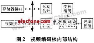
Compression coding consists of chip sz1510 and video frame buffer sdram (1m×16bit). sz1510 is a high-performance mjpeg and mpeg-1 encoding chip. It supports multiple working modes and bit rate modes. The internal video encoding core, tms320c54x High-performance dsp core, interface circuit, dma controller and clock generation circuit, etc. The structure of the video coding core is shown in Figure 2.
  
Â
The sz1510 input video stream is first subjected to video pre-processing, auto-reduction, scene switching detection, converted to video frame in cif format, and then subjected to motion estimation, motion compensation, discrete cosine transform/inverse discrete cosine transform and variable length. Encoding and other processing, generating mpeg-1 video elementary stream and storing it in sdram, at the same time, dsp core completes mpeg-1 audio coding and mpeg-1 format audio/video combination, generates mpeg-1 format system stream, and then passes Output port size is 256b fifo buffer for data output. When working normally, when frfo is full, a frdy (fifo read) interrupt is generated to inform the host to read the data in fifo. The host reads the data_out register through z56 times to complete the data reading. Take, when sz1510 issues an eod (end of data) interrupt, the data transfer ends.
2.2 Interface logic, control and storage part design
Various interface logics, address decoding, etc. in the system are implemented by epm7128. Its main functions include address decoding of sz1510 configuration register, address decoding of control and status signal registers, hardware reset signal generation, sz1510 and control module som2386. The interface, wherein the sz1510 configuration register and the control and status signal registers are connected to the som2386 as an i/o port, and the control and status signals are mainly used for outputting a self-test signal to the outside and receiving a recording switch control signal from the outside.
System control is done by som2386, a high-performance, compact embedded control module with an onboard embedded high-performance 16-bit processor, rdc161, which is internally 32-bit risc architecture and processed with 80c186 Compatible, its instructions are compatible with other x86 microprocessors. The module integrates system bios and 1.44mb flash memory on a single flash chip, supporting standard ide interface and two serial ports. The som2386 is connected to the host interface of the compression coding chip sz1510, and controls and configures the sz1510 through the host interface. In normal operation, the system stream of mpeg-1 format output from the host interface is sent to the storage unit as a file. The ide interface of the system is directly extracted from som2386, providing power for the dom (electronic hard disk), pin20 and +5v of the ide interface. The power supply is connected, and the remaining pin signals are defined in the same way as the ide standard. The serial port 1 of the som2386 module provides the rs-232 debug interface through the driver chip max232.
The storage unit adopts dom, which is composed of a control unit and a storage unit, and is a hard disk made by using a solid-state electronic device storage chip array. The interface specification and definition and the method of use are exactly the same as those of a general hard disk, and the outstanding advantage is that the volume is small. It has good shock resistance, wide operating temperature range, and only needs a single 5V power supply, suitable for airborne environments.
3 software design
3.1 sz1510 register configuration and binary code download
The external host implements the control and configuration of the sz1510 through the host interface and the two registers ioar (i/o address register) and iodr (i/o data register) inside the sz1510. When the host configures a register inside sz1510, it first writes the address of this register to ioar, and then writes the configured data to iodr, so sz1510 will automatically send the configured data to the register of the specified address, for example, the host writes during initialization. Data 0x44 to register 0x11 must be implemented by the following procedure:
a) write transfer: haddr=0, data=0x11;
b) write transfer: haddr=1, data=0x44;
Sz1510 has a program storage space inside, which is used to load the kernel binary code. This space is in block units. The size of each fast storage space is 256b. The code storage space of the dsp core is 0x280-0x2bf. The code encoding core code storage. The space is 0x0000-0x0004 and 0x000c. The specific process of binary code loading is as follows:
a) Write 1x01 to the 0x2e register, indicating that the external sdram is 1m×16bit;
b) Write 0x03 to the 0x0c register to enable frdy and eod interrupts;
c) Write 0x18 to the 0x11 register to select the internal memory write mode;
d) Write 0x20 to the 0x10 register, and set the output fifo size to 256b;
e) Load binary code for each block of memory, with the following: write 0x04 to 0x08 register, send start command, wait for frdy interrupt, clear frdy interrupt, write 256b to 0x01 register (data_in), wait for eod interrupt, clear eod interrupt.
3.2 i2c peripheral configuration
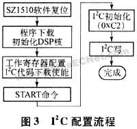
The configuration of the saa7113 is implemented by the sz1510 through its i2c bus. Due to the limitation of the internal storage space capacity of the sz1510, the loaded sz1510 kernel program code will overwrite the configuration code of the i2c peripheral. Therefore, the configuration of any i2c peripheral must be completed before the download and configuration of the sz11510 kernel program code. Sz1510 internal host port register 0x42-0x4f (each 8bit wide) interacts with the i2c service routine in sz1510, and configures any external device connected to sz1510 through i2c bus. All command codes must be written to sz1510 address as The command register at 0x08, sz1510, notifies the host by writing an interrupt with a code of 0x80 at address 0x0d. The i2c writing process is as follows:
a) write "initialize i2c" command code 0xc2 to the 0x08 register;
b) input data to sz1510 and write "i2c write" command code 0x0c to the 0x08 register;
c) After the data input is completed, sz1510 writes the interrupt command code 0x80 to the 0x0d register to notify the host.
The timing sequence of configuring saa7113 through the i2c bus of sz1510 is shown in Figure 3.
3.3 System software debugging and workflow
The software can be easily debugged by the rs-232 interface from the serial port 1 of the som2386 module. The cpu chip rdc1610 command is compatible with other x86 microprocessors, and the virtual display/keyboard technology is integrated in the module bios. Run the virtual display software pcvid3v0.exe on the PC to get the same effect as the local PC's dos environment. You can run all the commands under the dos directly. The debugging can directly access the sz1510 register and control and status port through the debug command. Registers, etc.
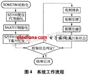
All software programs of the system are made into a batch file, which is stored in a specified directory of the virtual floppy disk on the som2386 module. After the system is powered on, the program under this directory is automatically run to control the system. After the system is powered on, the workflow of the entire system is shown in Figure 4.
4 Conclusion
Because the air background is relatively simple, the setting system works in vbr mode, which can reduce the code rate and maintain the image quality. The experimental results show that the system design structure is feasible. If 2gb electronic hard disk is used, the recording time can reach 8h or so. As the capacity of semiconductor memory continues to increase, the recording time of the system will be further extended. At the same time, in the future, the software can be modified to set the sz1510 to work in the mjpeg encoding mode to further improve the image quality of the recorded video. Therefore, the system has a large upgrade. The potential, compact structure, small size (size is only 90mm × 60mm × 25mm), light weight, easy to use, has been put into use on a certain type of aircraft, and the operation is stable and reliable, and achieved good results.
Dc Gear Motor,Geared Motor,Dc Gear Motor 12V,Low Speed Gear Motor
Changzhou Sherry International Trading Co., Ltd. , https://www.sherry-motor.com