Abstract: This paper introduces a simple, portable and multi-functional engine speed signal simulator. The PWM signal approximation method is used to generate the magnetoelectric signal whose amplitude varies with the engine speed, and the Hall signal is outputted by the output comparison method. The simulator can easily set engine parameters and modify engine speed online in real time and display in real time. The experimental results show that the simulator has the characteristics of high signal precision and large engine speed range.
Key words: engine; speed simulation; single chip; approximation
Introduction With the increasing complexity of the structure and control strategy of the electronic control system of the engine, the difficulty in research and development of the electronic control system and the amount of experimental work have been greatly increased, and the cost has also been greatly improved. The V-type development mode has become the mainstream of the engine ECU (Electronic Control Unit) development process. In the hardware-in-the-loop simulation, in order to cooperate with the development of ECU software, it is necessary to simulate the engine speed signal to verify the correctness of the software algorithm. .
A lot of research and development personnel have already done research in this area. For example, the engine speed simulator system developed by Zhang Jianyong of Tsinghua University uses the digital port to simulate the engine speed Hall signal in the large speed range; the portable engine operating condition signal simulator designed by Wang Yuming of Beijing Institute of Technology can simulate it more realistically. The type and shape of the engine sensor signal, the model-based signal generation method can better reflect the internal relationship of the sensor in the engine operating conditions change, and proposes a method of gradually transforming the Hall signal into a magnetoelectric signal through hardware; Beijing Urban Construction Design The speed simulator designed by Zhao Huawei of the Research Institute uses a hardware method to generate frequency square wave signals and current signals. It not only provides the square wave signal required by the engine, but also has high frequency adjustment precision and can realize current output.
These simulators are not yet capable of simulating an ideal magnetoelectric signal and are poorly adaptable to changes in engine parameters. In this paper, a method for generating standard magnetoelectric sinusoidal signals is proposed. Based on this, a portable and flexible engine speed signal simulation system is designed. The magnetoelectric sinusoidal signal can be obtained by hardware conversion and software approximation. The experiment proves that the magnetoelectric signal obtained by the former is not high precision, and the difference from the real magnetoelectric signal is large. Therefore, this paper adopts the software approximation method. Software segmentation approximation is divided into DA segment approximation and PWM segment approximation. The method of DA segment approximation needs to expand a D/A chip, and the conversion process needs to occupy a large amount of single-chip resources, which can not meet the high-frequency requirements. Therefore, this paper chooses the PWM segment approximation method. The system uses MC9S08 as the processor, sets the engine parameters through the panel keyboard or RS232 communication mode and changes the engine speed online in real time, and displays the information in real time through the LCD.
1 System overall design The schematic diagram of the engine speed simulator system is shown in Figure 1. The whole system includes a power module, a central processing unit, a panel key input module, a code wheel signal and a Hall signal input module, a liquid crystal display module, an engine signal output module, a conditioning circuit, a voltage dividing circuit, a relay driving circuit, and a communication module. 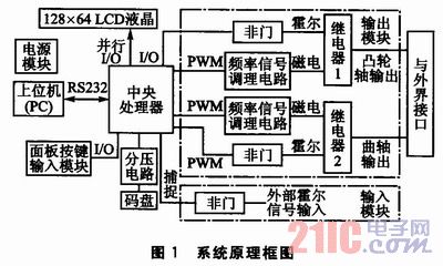
The power module is powered by 12 V and provides 5 V power and 15 V power to the entire system. Information such as engine model and sensor parameters can be selected from the panel key input mode or the upper computer input mode. The engine real-time speed can be selected from manual mode or automatic mode. If the manual mode is used, a specific value is input from the panel keyboard; if the automatic mode is adopted, the speed curve of the time change is input by the upper computer, or the real-time speed value is obtained by collecting the code wheel information. The LCD module displays the engine, sensor parameters and current engine speed. The output module includes a camshaft signal output and a crankshaft signal output, the relay 1 is a camshaft signal selection mode, and the relay 2 is a crankshaft signal selection mode. The input module has an external camshaft Hall signal and an external crankshaft Hall signal. After the two signals are collected by the single chip microcomputer, the output module converts and outputs the magnetoelectric signal.
2 Hardware Design
2.1 Processor Selection This simulator is an important tool in the development of automotive electronic systems. Therefore, it is necessary to select a vehicle-grade single-chip microcomputer that meets the most basic requirements such as wide temperature limit and strong anti-electromagnetic interference. At the same time, in order to reduce costs, low prices are also very necessary. The simulator chose Freescale's 8-bit processor MC9S08DZ60. It has 4 KB of RAM, 2 KB of EEPROM, 60 KB of programmable Flash; it contains 2 timing pulse width regulators, of which TPM1 has 6 PWM channels and TPM2 has 2 PWM channels.
2.2 Magnetoelectric signal conditioning circuit The actual motor speed of the magnetoelectric signal is a set of analog signals similar to sinusoidal signals. The amplitude is -1 to +1 at low speed and -15 to + at high speed. 15. The simulator uses a PWM signal to approximate the sinusoidal form to generate a magnetoelectric signal.
The magnetoelectric signal conditioning circuit is shown in Figure 2. 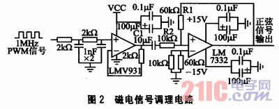
The signal conditioning process is divided into the following three parts:
1 plastic surgery. The input signal is a PWM signal with a fixed frequency of 1 MHz. The duty cycle changes according to the sinusoidal law. After being shaped by the LMV931, the sine wave is shifted upward.
2 filtering. The capacitor C1 acts as a filter to filter out the DC component of the signal, and the sinusoidal signal is shifted downward as a whole to obtain a standard sinusoidal waveform.
3 Zoom in. The maximum amplitude of the standard sine wave is only 2.5 V, which cannot meet the requirements of the magnetoelectric signal, so it is amplified once by the LM7332, and the magnification is β=R1/R2.
The signal transformation process is shown in Figure 3. 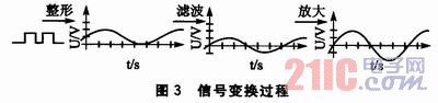
3 Software Design The entire software part is divided into simulator configuration status and simulator output status. Configuration Status The main function is to set engine parameters via panel keypad or RS232 communication. The main function of the output state is to output the crankshaft signal and camshaft signal at the current demand speed based on the combination of engine parameters and sensors.
3.1 Approximating the magnetoelectric sinusoidal signal The simulator generates a magnetoelectric signal by means of a PWM signal software approximation. As the number of segments in a cycle increases, the accuracy of the approximation increases. However, in order to prevent the program from entering and leaving the interrupt frequently at high speed, it will affect the operation of other parts of the program. Considering the accuracy of the approximation, the bus frequency of the MCU and the symmetry of the sinusoidal signal, a sinusoidal period of the camshaft magnetoelectric signal is equally divided into 20 equal parts, and the PWM signal of different duty cycles is used to approximate 20 segments of the sinusoidal signal, as shown in the figure. 4(a); divides a sinusoidal period of the crankshaft signal into 12 equal parts and approximates 12 of them by PWM signals of different duty cycles, as shown in Fig. 4(b).
Calculate the approximate time interval between points. Calculated as follows: 
Among them, TimeIntervalCrank is the interval count value of the crankshaft signal approaching each point time; TimeIntervalCam is the interval count value of the camshaft signal approaching each point time; fbus is the clock bus frequency (Hz); Cranknumber is the number of crankshaft teeth (60, 48); Camwidth is Camshaft tooth width (1, 2, 3...); n is the engine target speed (rpm).
In Fig. 4, the solid line is the approximated target curve, and the dashed line is the approximated curve. The approximated curve is shifted to the right by a small phase relative to the target curve. In the program, the start time of the approximation should be advanced to eliminate the approximation phase error. . 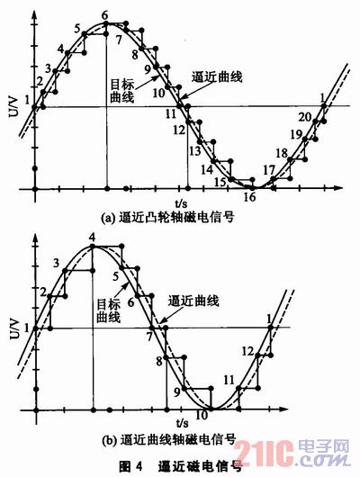
The value of the modulus register of the PWM channel is constant at 19, and the value of the value register corresponding to the maximum value of the sine signal is Rang, as shown by the "6" point and the "4" point in FIG. In order to ensure that the amplitude of the sinusoidal signal changes with the value of the rotational speed, Rang increases as the engine speed increases, Rang = Rang (nspeed).
When approaching a sine wave of a crankshaft signal, the sine values ​​corresponding to the points in the sinusoidal signal are listed in Table 1. The value of the MCU value register corresponding to each point is TPM2CV0=Rang(nspeed)×Sin(Number). Similarly, the value TPM2CV1 of the 20-point corresponding value register of the camshaft magnetoelectric signal can be obtained. 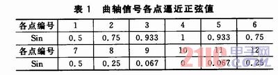
In order to save the time occupied by the MCU multiplication and division operation, the register values ​​corresponding to each point are made into an array in the program and directly called. If you want to approximate a sine wave with the opposite polarity (negative negative and positive) as in Figure 4, simply reverse the approximation order of the points, that is, the approximation order is 20, 19, 18, ..., 2, 1.
3.2 Generate camshaft signal and crankshaft signal The crankshaft signal flow is shown in Figure 5. First determine the crank signal pattern. 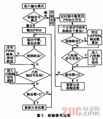
If the mode is Hall, the PWM Hall signal is output. The number of crankshaft teeth is accumulated in the overflow timing interrupt. If it is determined that the crankshaft missing teeth are valid, the PWM frequency is changed, and after two missing tooth signals are obtained, one cycle ends and the crankshaft teeth counts again. It is judged in the main program when the camshaft signal is output.
If the mode is magnetoelectric, the PWM approximation signal is output and the timing is approached. In the timed interrupt, the duty ratio of each point is set to be close, and the number of approach points is recorded. After the end of one sine period, the number of crank teeth is incremented by one. If it is judged that the missing tooth is valid, the PWM signal of the duty ratio corresponding to the constant "1" point in Fig. 4 is output, and one crankshaft cycle ends after the two missing teeth, and the crankshaft teeth counts again. It is judged in the main program when the camshaft signal is output.
Cam axis signal flow: If the signal mode is Hall, the Hall signal is output through the I/O port in the main program. If the signal mode is magnetoelectric, the output approaches the PWM signal, and the duty ratio of each point is set in the timed interrupt, the number of approach points is recorded, and the approximation timing is ended after one sine period ends, and the constant "1" point in FIG. 4 is output. The PWM signal corresponding to the duty cycle.
4 Experimental verification Set the simulator parameters as follows: the crankshaft teeth are (60-2) teeth, the camshaft teeth are (4+1) teeth, the camshaft tooth width is 6 crankshaft tooth widths, and the multi-tooth super missing teeth 12 °CA (crank angle is expressed in °CA), cam multi-tooth super-cam 1 tooth is 60 °CA. The signal shown in Fig. 6 is observed by an oscilloscope. 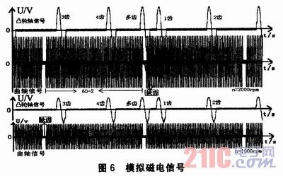
The crank signal mode and the camshaft signal mode shown in Fig. 6 are both magnetoelectric. The analog signal satisfies the set parameter requirements, and the amplitude and phase are accurate, the relative phase is accurate, and the frequency is stable. The rotational speeds of the upper and lower sets of signals were 2000 rpm and 1000 rpm, respectively. As can be seen, the amplitude of the magnetoelectric signal varies with the rotational speed. 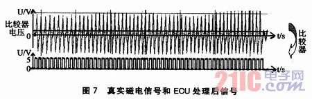
The actual measured magnetoelectric signal and the signal processed by the ECU are shown in Fig. 7. The signal is converted into a square wave signal by the comparator in the ECU, and is then collected by the single chip microcomputer. After the simulated magnetoelectric signal passes through the comparator, it is also converted into a square wave signal. Although the analog signal is different from the real magnetoelectric signal, the same square wave signal is obtained after the comparator, which is the same signal for the single chip microcomputer, so the analog signal can replace the real magnetoelectric signal.
5 Conclusion Experiments have shown that the PWM signal approaching the sinusoidal signal can simulate a standard magnetoelectric sinusoidal signal on an 8-bit machine, and this signal can replace the real magnetoelectric signal. The simulator system accurately simulates engine speed signals from 100 to 6000 rpm to meet design requirements. Due to the limited processing capacity of the 8-bit single-chip microcomputer, the simulator cannot realize the continuous and linear change of the amplitude of the magnetoelectric signal with the rotation speed, but does not affect the function of the simulator. If used instead. The DSP processor can be implemented by means of series approximation or iterative approximation.
This article refers to the address: http://
PTFE Fabric With Silicone Adhesive
Strong Adhesive Tape,Silicon Tapes,Silicone Fabric,PTFE Fabric With Silicone Adhesive
TAIZHOU YAXING PLASTIC INDUSTRY CO., LTD , http://www.yaxingptfe.com