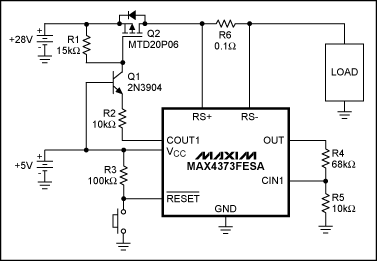
Designed with the MAX4373 high-side current-sense amplifier, the circuit can operate up to 28V. Just a generic NPN transistor.
This article refers to the address: http://
The MAX4373 is a high-side current-sense amplifier with a comparator and reference. The comparator's latch-out output (COUT1) allows the device to form a circuit breaker (refer to Figure 2 of the device data sheet). However, the data sheet gives a circuit that is only suitable for a supply voltage range of +2.7V to +5.5V. By adding a general-purpose NPN transistor, the voltage range can be extended to 28V, as shown in Figure 1.

Figure 1. In this circuit breaker, NPN transistor Q1 expands the swing of comparator output COUT1.
Under normal operating conditions, the open-drain comparator output is low, allowing 430μA of nominal current to flow from the emitter of the transistor through R2 into COUT1. The same (approximately the same) current flows through the collector and R1, producing a VGS voltage slightly above -6.4V, driving the p-channel MOSFET.
In this design, the current limit of the circuit breaker is 900 mA. Since the MAX4373FESA is capable of delivering 50V/V from the current-sense resistor to the output, this device was chosen. When a current of 900 mA flows through the current-sense resistor R6 of 100 mΩ, a voltage drop of 90 mV is generated, which is multiplied by 50 times the gain, and a voltage of 4.5 V is obtained at the OUT terminal. Comparator CIN1 input threshold is 600mV, choose 6.5:1 resistor divider network to get our required set value. R4 selects 68kΩ and R5 is 10kΩ, which gives an actual load current threshold of 936mA, which is close enough to our target value.
When the load current exceeds this threshold, the comparator output is latched to a high impedance state. The transistor enters the cut-off region and the MOSFET turns off. After the fault is removed, the circuit can be restored to the normal operating mode via the reset button.
This circuit is suitable for high voltage applications (in this case with +28V) and voltage is at least twice the VCC voltage. In addition, VCC is limited to a maximum of +5.5V, which is within the limits of the comparator output. The difference between the values ​​of the resistors R1 and R2 introduces a certain gain, which can provide a higher MOSFET driving voltage, thereby reducing the loss of the MOSFET on-resistance.
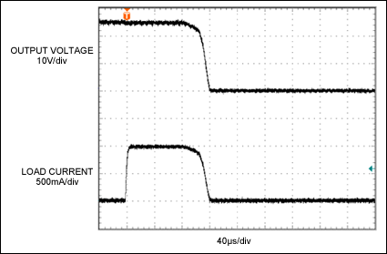
The circuit's response time to overcurrent faults is approximately 100μs (Figure 2), and its response characteristics remain stable for overcurrent conditions 10% above the threshold (unlike mechanical thermal circuit breakers).

Figure 2. From the load current waveform, it can be seen that the circuit breaker shown in Figure 1 is triggered when the current reaches 110% of the nominal 900 mA threshold. The response time is approximately 100 μs.
N-NET Repeaters (single-/multi-mode converters) are applied in 100Mbps fast Ethernet /1000Mbps Gigabit Ethernet Network which is wired with both single mode fibers and multi-mode fibers. It can not only fulfill the conversion of single mode and multi-mode at 1310nm wavelength, but also that of 850nm/1310nm and 1550nm wavelengths, which functions as a relay and then makes multi-mode fibers transmit farther. It supports transmission in multi-mode dual fiber, single mode dual fiber and single mode single fiber.
Signal Booster Repeater,Wireless Repeater,Dual Band Signal Repeater,Mobile Repeater,3R Repeater, 10G 3R Converter Repeater
Shenzhen N-net High-Tech Co.,Ltd , http://www.nnetswitch.com