The steering system is an important part of the car, its performance directly affects cars with stability and security. Early automotive steering system is purely mechanical steering system, no power steering power provided entirely by the driver, poor driving experience. From the 1930s, the gradual emergence of the power steering system. At present, there are three main forms of automotive power steering: Hydraulic Power Steering (HPS), Electric Hydraulic Power Steering (EHPS) and Electric Power Steering System (EPS). Compared to the first two, EPS assist torque provided by the motor, no oil system to a large extent reduce the complexity of automotive steering systems, and in fuel efficiency, modular, boosting effect and environmental friendliness and other areas has obvious advantages . EPS assist motor in accordance with the different positions, it is divided into a column assist type EPS system, a rack assist type, pinion assist type and a double-pinion assist type in the four types of gear and steering column assembly. Pinion and steering column assist are used in light vehicles, and double pinion assist is used in heavy vehicles. They are composed of three basic components: an electric control unit (ECU), a booster motor and a torque sensor mounted on the steering column. For the small car, the EPS controller is designed with the 16-bit single chip MC9S12DP256 of Freescale Company as the core.
This article refers to the address: http://
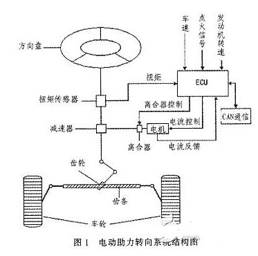
1 Electric power steering system structure and working principle
The structure of the electric power steering system is shown in Figure 1. It is mainly composed of a steering wheel, a torque sensor, an electronic control unit (ECU), a motor, an electromagnetic clutch, a speed reduction mechanism, and a rack and pinion steering gear. After the engine is ignited, the steering torque is measured by a torque sensor mounted on the steering shaft and sent to the ECU. The ECU calculates a boost characteristic curve and a control strategy based on the torque and the vehicle speed. The optimum current required by the motor, thus controlling the output torque and direction of rotation of the motor, and then applying it to the steering mechanism via the reduction mechanism, ultimately resulting in a steering force that is compatible with the driving conditions to assist the driver in steering.
2 control strategy
2.1 Establishment of EPS model
According to Newton's law, a mathematical model of the steering system can be established.
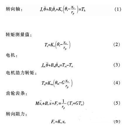
Wherein: Th is a steering wheel input torque, Js of the steering column, the moment of inertia plate assembly, Bs damping coefficient of the input shaft, the torque sensor is a stiffness coefficient Ks is, Tm motor output torque, Km is the stiffness coefficient of the power steering motor and the reduction mechanism, Jm is the driving motor moment of inertia, Bm is the assist motor damping coefficient, M is the rack quality, Br is the rack and steering wheel viscous damping coefficient, Kr is the rack equivalent stiffness, G is the assist mechanism transmission ratio, and rp is the pinion radius , θs is the steering wheel angle, θm is the motor rotation angle, xr is the rack displacement, and Fr is the steering resistance.
2.2 Assist characteristic curve design
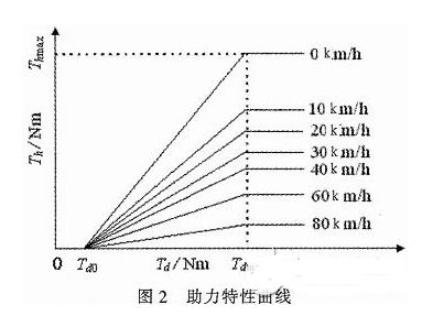
The EPS assist characteristic is the relationship between the driver input torque and the motor assist torque (assisted current). During the driving process, the steering resistance decreases as the vehicle speed increases. In order to obtain the portability of the steering at low speed and the stability during high-speed driving, the motor assist torque decreases with the increase of the vehicle speed under the same driving conditions, and the motor does not assist when the vehicle speed exceeds a certain range. . There are three common power assist curves: linear, polygonal, and curved. The linear assist characteristic curve is simple in form and easy to adjust and implement in practice. Therefore, the linear boosting characteristics are used in the design of the controller. The linear assist characteristic can be expressed as the following functional relationship:
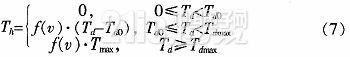
Among them: Th is the motor target torque, f(v) is the vehicle speed induction coefficient, Tmax is the motor maximum assist torque, Td0 is the driver input minimum torque when starting power, and Tdmax is the driver input torque when the motor provides maximum power.
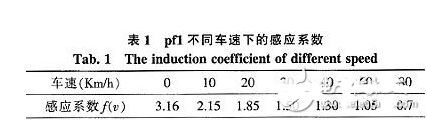
The assist characteristic parameters are determined: Td0 = 1 Nm, Tdmax = 7.6 Nm, Thmax = 21 Nm. The vehicle speed induction coefficient is determined according to the rules shown in Table 1 (final correction is required after the actual vehicle test). When the vehicle speed exceeds 80 km/h, the motor does not assist.
According to the above parameters, the power assist characteristic curve design is shown in Figure 2.
The motor target current can be obtained from equation (8):
Where ki is the motor torque factor and G is the motor reduction mechanism transmission ratio.
2.3 Control algorithm
The EPS system control is the control of the magnitude and direction of the motor current. The quality of its control algorithm directly affects the performance of the steering system. This paper adopts the PID control algorithm widely used in the field of industrial control. The PID control has high stability and reliability, strong real-time performance, simple control and debugging method, and is easy to implement. It is suitable for the control of automotive electric power steering system. Therefore, PID control is the main control strategy of the current EPS control system.
The expression of the PID control can be expressed as:
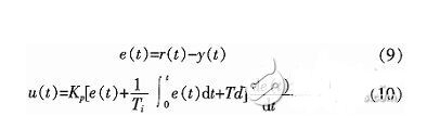
Where: r(t) is the target value of the assist motor current, y(t) is the actual output value of the control system, u(t) is the output signal of the PID controller, TI is the integral time constant, and Td is the differential time constant. The core of the EPS control system is a microcontroller that uses digital signals. Therefore, the following formula (10) needs to be processed:
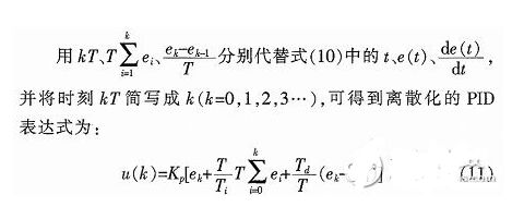
In order to reduce the amount of calculation and improve the real-time performance of the steering system, this design uses incremental PID control with the increment of control quantity Δu as the output of the controller. The implementation method is as follows:
Set the target current of the assist motor to i, and the actual current assist current is io, then the control deviation is:
Ek=i-io (12)
â–³u=u(k)-u(k-1) (13)
The target current of the assist motor can be calculated by the MCU according to the current vehicle speed, input torque and assist characteristic curve. Then, the corresponding PWM increment Δu can be obtained from equations (11), (12), and (13).
Electric Spiral Stove,Cooking Plate Stove,Electric Cook Stove,Spiral Hot Plate Electric Stove
Shaoxing Haoda Electrical Appliance Co.,Ltd , https://www.hotplates.nl