Motors for applications such as fans, pumps, air conditioners, refrigerators, washing machines, elevators and transmissions consume more than half of the world's electrical energy, most of which use high-energy electromechanical drives that simply turn the motor on and off. Replacing these inefficient motors with frequency conversion solutions in appliance applications can cut energy consumption by up to 60%. Most home appliances use general-purpose DC motors or single-phase AC induction motors. The speed control method is quite rough, either with breaking control or with thyristor to control the conduction phase angle. The typical system efficiency can reach 50%. . However, with the advent of high-efficiency power devices and advanced digital controllers, it has become possible to apply more efficient motor and control technology to the latest appliances.
AC motor selection
The shaft end output torque of any AC motor is dependent on the coupling angle between the stator and rotor fields. The magnetizing force of the stator winding current interacts with the air gap flux generated by the rotor to generate a torque that tends to align the rotor flux with the stator magnetic field. When the stator magnetizing current vector is 90° out of phase with the rotor flux vector, the moment Reaches the maximum value. In the DC motor, the permanent magnet is fixed, and the switching action of the commutator and the brush ensures that the armature magnetic field is properly aligned with the stator pole. In an AC motor, the air gap magnetic field rotates, but a constant torque can be generated as long as the rotational frequencies of the stator and rotor fields remain synchronized.
There are two main types of AC motors: synchronous motors and inductive motors (also commonly referred to as asynchronous motors). In a synchronous AC machine, the rotor field is generated by a DC current in the rotor winding or by a permanent magnet. To generate a constant torque, the stator current must be synchronized with the rotor angle and the rotational frequency. In an induction machine, the rotor magnetic field is formed by the induced current generated by the stator in the rotor through the transformer effect, so that the frequency of the stator and rotor magnetic fields can be self-synchronized. When the induction motor is stationary, the magnetic flux coupled with the rotor coil is the same frequency as the stator magnetic field, so the rotor current is also the same frequency as the stator current. When the induction motor rotates, the coupling frequency of the rotor flux is the difference between the stator frequency and the rotor rotation frequency. The value, the so-called slip frequency, if the motor rotates at the stator frequency, the rotor flux is constant and the rotor current cannot be induced, so the torque output is zero. Inductive motors always operate at a certain speed slightly below the stator frequency. If the load increases, the speed decreases and the slip frequency increases, thereby inducing a larger rotor current to produce a higher torque.
Inductive motors are widely used in industrial and household appliances, especially where fixed speeds are required. An important advantage of induction motors is that they can be directly connected to the AC grid and started up. Conversely, the amplitude and frequency of the open-loop output voltage of the synchronous motor must be fully matched to the grid before it is connected to the AC grid. Large synchronous motors are commonly used in power generation, and multiple generators are connected to the same public grid.
In frequency conversion applications, selecting a motor for the drive system is non-dominant. Inverter drives for inductive motors use a wide range of open loop voltage/frequency speed control schemes. If a speed sensor is used, it is also possible to achieve closed-loop control of the induction motor, that is, by changing the slip frequency of the motor to control the torque generated by the motor. However, since the rotor current cannot be measured and the rotor circuit time constant is large, it is difficult to achieve high dynamic control of the induction motor. In contrast, as long as the angular position of the rotor is known, the high dynamic torque control of the synchronous machine can be achieved very conveniently.
Permanent magnet synchronous machines (PMSM) have been used in the industrial servo field for many years. Thanks to the permanent magnet rotor, this motor is very efficient and offers a much higher continuous torque than an induction motor of the same size. However, it is necessary to detect the position of the shaft angle with a Hall sensor or a position sensor such as a resolver. The demand for the rotor angular position sensor has limited its application to the high-end industrial drive field, but it has developed in recent years. The sensor "control algorithm has increased its use in the field of home appliances.
Compressor speed control is one of the initial applications of permanent magnet synchronous motors in the field of home appliances. Conventional compressors for air conditioners and refrigerators use induction motors that operate at a fixed speed depending on the grid frequency. The size of the compressor must meet the maximum load condition after power-on, but in normal operation, the compressor must be maintained at the set temperature. A fairly low duty cycle cycles intermittently. However, with compressor speed control, the most efficient working speed can be selected for normal operation. The use of speed control alone can increase efficiency by more than 30%. In addition, due to the higher efficiency of permanent magnet motors, it can also increase the efficiency by 15%. Today, in regional markets that focus on energy costs, such as Japan, almost 90% of air conditioners and more than 50% of domestic refrigerators have adopted compressor speed control.
The original sensorless controller used a six-shot commutation phase sequence to drive the motor windings and estimated the rotor position by monitoring the back EMF of the open winding. This method provides highly robust speed control but does not provide smooth motor torque. The primary reason is that when using a six-shot phase sequence, in order to generate a constant torque, the motor must have a trapezoidal back EMF waveform instead of the usual sinusoidal waveform. Second, the bigger problem is that the current switches to the subsequent phase during the commutation process. The torque introduced during the winding fluctuates. Since the motor back EMF accelerates the current decay of the exit phase and prevents the current from entering the phase from rising, the higher the operating speed, the worse the problem becomes. High-order harmonic components of motor torque fluctuations are prone to mechanical resonance of the system, producing audible noise in fans, washing machines, pumps, and air conditioners. However, such a controller is very simple and easy to implement, so it is still used in situations where smooth torque control is not required.
Another alternative sensorless control scheme has become popular in recent years due to the use of low-cost controllers based on DSP and RISC to implement more complex control algorithms. The “latest sensorless†control allows the permanent magnet synchronous motor to be driven with a sinusoidal voltage and current waveform, and the rotor position is estimated based on the measured value of the motor current. This algorithm can effectively provide a constant torque without the aforementioned six-shot control. The audio noise problem with the device. In addition, the algorithm can be implemented by a new controller hardware architecture and can effectively implement complex control without any software coding. The core of the dedicated integrated design platform is the latest sensorless controller, focusing on the challenges of additional integration functions such as control and power electronics. With the compatible chip design, the platform design method can be completed, with the focus on digital control chips. A three-phase inverter driver chip and a high voltage current sensing chip are provided between the power stage and the power stage.
Latest sensorless permanent magnet synchronous motor control without software
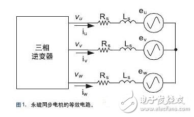
The latest sensorless algorithm is based on a simplified model of a permanent magnet synchronous motor as shown in Figure 1. The motor winding back EMF waveform is a sinusoidal function of the rotor angle and can therefore be used to measure the rotor angle. The back EMF can be calculated by measuring the current flowing into the stator coil when the stator voltage is applied. To simplify the mathematical operation, the three-phase circuit can be transformed into a two-phase equivalent model by using the Clarke transform, so that the back potential can be expressed by the sine and cosine functions of the rotor angle. The equivalent circuit can be described by the following equation:
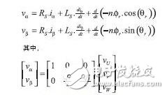
To extract the rotor angle, the back EMF term can be integrated to calculate the rotor flux, which is independent of speed. Finally, since the ratio of the sine and cosine flux terms is independent of the magnitude of the flux, it can be used to accurately estimate the angle and velocity of the rotor.
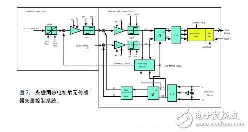
Angle estimation is a key part of implementing control algorithms, but many other functions are still required to implement the control system depicted in Figure 2 in the block diagram. The controller consists of a speed outer ring and a stator current inner ring, which can respectively generate a reference torque or control the voltage applied to the winding. The stator current control loop is realized by Field Oriented Control (FOC) technology in a rotating reference coordinate system. The vector is rotated as a function of the rotor angle, and the stator current is converted into two quasi-DC components ID and IQ. The IQ current component is orthogonal to the rotor flux and produces a torque with a reference value from the speed loop output. The ID current is aligned with the rotor flux to enhance or weaken the rotor flux. The ID reference is zero in most speed ranges. However, if it is required to extend to the constant power speed range, the field weakening control can be realized by the ID setting, which is very useful for applications such as washing machines that require high rotational speed.
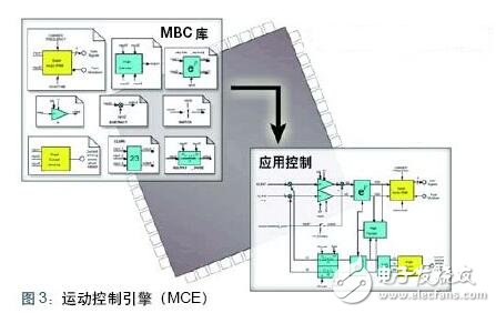
The sensorless field oriented control algorithm can be implemented with a completely new controller architecture. Each function of the control system shown in Figure 2 can be implemented with a hardware macroblock instead of software. Functions such as proportional integral control, vector rotation, and Clarke transform are common to all AC motor control systems. As shown in Figure 3, the Motion Control Engine (MoTIon Control Engine) library contains AC motor control modules and other general purpose modules. By acquiring the motor control chip, you can acquire the MCE library, as well as analog input and space vector PWM control. Developers can use graphical tools to drag components from the MCE library into their own control system design, and then use the graphics compiler to translate the control design into MCE sequence instructions, connecting the hardware macros in the correct order to implement their own control system. This method eliminates the need for software coding during development, saving time and reducing errors.
Washer motor control options
Precise control of the drum speed is important for controlling the washing action of drum-type washing machines and pulsator washing machines. Drum washing machines have been used in Europe for many years and are now becoming more popular in North America. The pulsator type washing machine requires the clothes to be completely submerged in the water, and the damper type of the drum type washing machine only needs to be filled with water at the bottom of the drum, which can significantly reduce the amount of water used and fundamentally save the energy required for heating the washing water.
In the drum type washing machine, the key factor determining the washing action is the drum rotation speed. The critical speed of the drum depends on the radius of the drum. Above this speed, the clothes will stick to the drum wall; at this speed, the centrifugal force generated by the rotation is just balanced with the gravity of the clothes; below this speed, the clothes will stick to the drum. On the wall, until the gravity component in the radial direction exceeds the centrifugal force, once it is raised to the angle, the laundry will fall to the bottom of the drum. Since the drum rotation speed determines the washing power of the laundry, a gentle washing cycle can be selected for the fine fabric. In the conventional pulsator type washing machine, the agitating action is generated by the mechanical structure using the gear case and the clutch, and therefore, the introduction of the rotational speed control system can not only simplify the mechanical system but also control the washing cycle. Controlling the speed and angle of the washing action allows the system designer to better handle the washing action, thereby developing a more water-saving washing cycle.
Many of the motor speed control options described above can be applied to the washing machine. Instead of using an AC motor, the European drum-type washing machine uses a common "brushed" motor, while the American washing machine uses a larger drum size, so the motor's power range needs to exceed the general motor solution.
Although three-phase induction motors are still in use, permanent magnet synchronous motors are becoming the preferred solution in recent years. The magnetic field of the induction motor comes from the current and must be generated by the stator excitation current component. To generate the torque, the current needs to flow through both the stator and the rotor winding, and the total copper loss is more than twice that of the permanent magnet motor. Because permanent magnet synchronous motors are more efficient than induction motors, steel and copper are used less than induction motors of the same power class. In the past few years, global copper and steel prices have almost doubled, while the cost of magnetic materials has declined. In this way, permanent magnets not only mean high efficiency, but also mean no longer expensive. Many home appliance manufacturers are using permanent magnet synchronous motor solutions for pulsator and drum type washing machines, some of which are beginning to develop controllers based on motion control engine (MCE) based control chips.
Conclusion
An integrated design platform can now be used to simplify the design process and reduce costs of advanced energy-efficient home appliance motor drive applications. At the heart of the design platform is a dedicated sensorless control chip and a companion Motion Control Engine (MCE) that includes all the control elements necessary to achieve closed-loop sensorless sinusoidal control, unlike other DSP or MCUs, without tedious and error-prone Software programming link.
200V DC Electronic Load System
200V high precision DC Electronic Load provides 3 types power combination which is 39600W/52800W/66000W,highest current can reach 3000A. The DC Electronic Load System supports four kinds of basic operating mode including CV (constant voltage), CC (constant current), CR (constant resistance), CP (constant power), to satisfy a wide range of test requirements., as well as CV+CC, CV+CR, CR+CC these 3 complex operating modes.
Additionally , programmable DC electronic load can also have higher voltage for options which 600V DC Electronic Load sytem and 1200V DC Electronic Load System .
Key features are as below for your reference:
â— Flippable front panel and color touch screen allow convenient access and operation
â— Provides four kinds of basic working mode such as CV/CC/CR/CP, and CV+CC/CV+CR/CR+CC complex operating modes
â— Adjustable current slew rate, adjustable CV loop speed
â— Ultra high precision voltage & current measurement
â— 50kHz high-speed CC/CR dynamic mode
â— 500kHz high-speed voltage and current sampling rate
â— Timing & discharging measurement for batteries
â— Short circuit test mode
â— Auto mode function provides an easy way to do complicated test
â— V-monitor/I-monitor
â— Full protection: OCP, OPP, OTP, over voltage and reverse alarm
â— Front panel USB interface supports data import and export
â— Using standard SCPI communication protocol
â— Smart fan control with lower noise and better for environment
200V slew rate DC E-load, CV loop speed DC electronic load, 200V high precision DC electronic load
APM Technologies Ltd , https://www.apmpowersupply.com