Introduction With the large-scale application of digital TV services, more and more TV programs are available for users to choose from, and content is becoming more and more abundant. The supervision of TV programs has become a problem. In a prefecture-level city, there are at least 40 sets of programs to be broadcast. If the TV program monitoring is performed manually, it is not only a heavy workload, but also a high cost, and the effect is not satisfactory. At present, the relevant monitoring equipment in the domestic market is very functional, but the price is very expensive. Is there an economically viable way to monitor and handle TV signal failures? This article will explore this issue.
This article refers to the address: http://
1 Digital TV and its advantages Digital TV is the latest and best quality broadcast mode of cable TV. It is a new method of transmitting, transmitting and receiving moving image (including sound) information in digital mode (combination of 0 and 1). Color TV system. An image consists of a number of pixels, each of which has three colors, that is, each pixel uses three sets of numbers to express its brightness and color. The higher the image resolution, the more pixels there are, and the greater the amount of data representing an image. Therefore, the image information expressed by numbers is compression-encoded according to a certain rule (algorithm), and after transmission, it is restored to the original image signal by decoding at the receiving end. Nowadays, the digital TV service is popularized and digitally compressed and encoded by a video encoder at the front end of the broadcast, which is converted into a digital signal. The latest international QAM modulation technology is used to make the signal's anti-interference ability in the transmission process greatly Improvement. The quality of the signal transmitted to the user's home is almost close to the source of the program. Snowflakes, stripes, and blurs that are common in analog TVs will no longer appear. Users who originally watched analog TV only need to configure a digital set-top box to use the analog TV to watch digital TV programs, enjoy various services, and selectively pay to watch their favorite TV programs.
Digital TV has the following advantages:
1 The image quality is high. In the digital mode, since the television signal is not easy to introduce noise and interference during transmission, the image quality of the studio can be almost reached at the receiving end.
2 program capacity is large. Digital television transmits a compression-encoded signal that occupies a relatively narrow frequency band. For example, a satellite transponder can only forward a set of analog TV programs, but can forward 4 to 5 sets of digital TV programs of the same level of clarity. The current 550 MHz cable TV network can only transmit 60 to 70 sets of analog TVs, and can be used to transmit digital TVs. The program capacity can exceed 500 sets.
3 sound quality is good. At present, the analog TV's sound is mono (even with the sound of the sound, it is just a simple two-channel), and the image bandwidth is limited to 5 MHz; and the digital TV can transmit more than 4 surround sound, really Get a home theater-like sound.
2 Digital TV faults and solutions The faults that often occur in the monitoring of TV programs are as follows: no sound signal; no image signal (black screen); image garbled or freeze.
The cause of the failure:
1 The signal source is lost, such as satellite receiver error or crash, video broadcast server failure, etc.;
2 Failure occurs through digital TV front-end equipment (such as encoders, QAM modulators, etc.).
At present, the method of manually resetting or restarting the power supply is used to monitor the related channel fault handling. As the number of programs increases and the sudden increase in failures, the work intensity and pressure of the duty personnel suddenly increase. How to reduce the workload of the staff, while making fault monitoring fast and efficient, has become an urgent problem to be solved.
3 The goal of digital TV fault monitoring is to implement related monitoring and alarm on the basis of the existing STB set-top box. Mainly test three aspects:
1 No sound detection. The sound source after the relevant channel shaping is sent to the monitoring system is automatically determined by the control system. Once a silent fault occurs, an automatic alarm is issued to remind the on-duty personnel to quickly check the fault and resume the normal operation of the digital television broadcast system.
2 No image failure detection. The monitored image waveform is sent by the monitoring system. Once there is no image, it will automatically alarm to remind the on-duty personnel to quickly check the fault and resume the normal operation of the digital TV broadcast system.
3 image flower screen or freeze detection. This is a feature of this inspection system. Through the USB CMOS CCD interface of the dual-core processor PA1688, the TV image data of the tested channel is periodically collected. As long as the data does not change or change little in a few cycles, the channel failure can be determined and the alarm is automatically triggered.
4 Digital TV fault monitoring system design
4.1 The overall design of the overall design is shown in Figure 1.
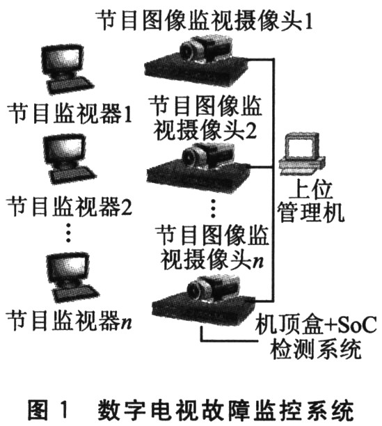
The program monitor is used to play the specified related program; the program image surveillance camera is used for monitoring and collecting the program image failure (such as the flower screen); the set top box + SoC detection system is used to integrate the SoC detection system and the set top box, and the SoC system is set to the set top box. The control channel is switched and monitored; the upper management machine is used to summarize and count the fault data of each lower management machine, and generate a report.
4.2 Hardware Design
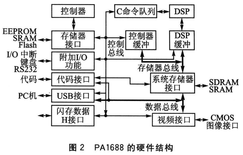
4.2.1 Introduction to PA1688 PA1688 is a complete solution for network voice communication terminals. It is specially designed for low-cost, high-performance network voice and video. Only its CMOS image interface is used here. .
The PA1688 is a dual-processor integrated chip with an on-chip integrated controller, digital signal processor and other necessary interface circuitry. The design not only ensures that the chip itself is easy to develop, the cost is low, and that all peripheral interface chips are fully supplied and inexpensive. The hardware structure of PA1688 is shown in Figure 2.
The core of the PA1688 chip mainly consists of two parts:
1 controller. The enhanced Intel MCS-51 instruction set is compatible with the controller and is responsible for system control, system interface processing, and various protocol processing (such as TCP/IP, H.323, etc.). The PA1688 chip has an operating clock of 4 to 8 clock cycles (average of 6 clock cycles) and a maximum operating clock frequency of 50 MHz, which is equivalent to the operating speed of the standard MCS-51 of 100 MHz.
2DSP. The ADSP2181 instruction set is compatible with digital signal processors and mainly performs speech and image codec operations. The maximum operating clock frequency is equivalent to the standard 2181 of 33 MHz. In addition to the above two parts, the chip also provides a wealth of peripheral interfaces, mainly including RS232, USB, SDRAM, AC97codec, SRAM and Key-Pad. Among them, USB, SDRAM and AC97codec are featured.
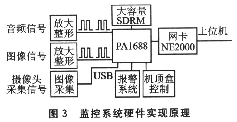
4.2.2 Hardware Implementation The low-cost PA1688 dual-core processor is used as the core device of the monitoring system. The hardware implementation principle is shown in Figure 3.
4.3 Software Design The software uses Keil C51 to achieve the following functions:
1 Complete the acquisition and processing of the audio signal. The audio signal is shaped to form a TTL level. Under normal circumstances, the TTL level after shaping is high, and if it is silent, it is low. Use this feature to monitor the sound.
2 Complete the monitoring and processing of the image with black screen or no signal. The method is similar to the fault handling of audio signals.
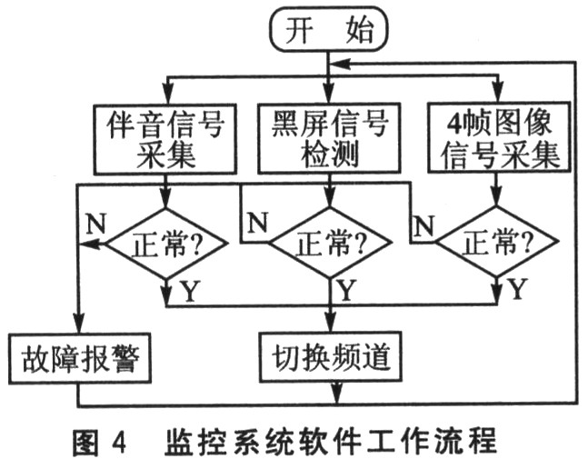
3 Monitoring and processing of issues such as channel screens. This is a major feature of the system, using DSP data acquisition to determine image quality failures. Due to the large amount of memory space occupied by the image acquisition and storage, taking into account the characteristics of the image, one frame of image is taken every second for the channel within 4 s. Then compare the 4 frames of images. If the data is basically the same, it means that the image is faulty and needs an alarm reminder.
At present, the program source is relatively rich, and there are many monitoring channels (generally reaching 40 to 50 channels), and the switching and detection time of each channel is about 6 s. In this case, if only one detection system completes the monitoring of channel 1 to channel 50, it takes about 300 s, which greatly exceeds the specified failure alarm time. To this end, the monitoring system segmentation detection mode is adopted, so that the monitoring time is greatly shortened. This has the advantage of increasing or decreasing the number of monitoring systems depending on the number of channels to ensure the quality and effectiveness of the monitoring.
The software workflow is shown in Figure 4. The program was simulated on the Proteus simulation software and basically met the design requirements.
Conclusion <br> The low-cost dual-core processor PA1688 can better solve the problems of large workload and inaccurate monitoring in digital TV fault monitoring. However, there are many types and phenomena of TV faults, not only the three cases mentioned in this article, which requires us to establish a database of fault phenomena. The software can be upgraded to handle all types of failures simultaneously.
SHAOXING COLORBEE PLASTIC CO.,LTD , https://www.colorbeephoto.com