Battery-powered devices are an important part of our daily lives, and the charging burden of these devices is more important than ever. In the past few years, there have been many new ways to solve the problem of longer charging times, allowing users to complete charging in minutes instead of hours.
This article will focus on the trend of fast charging and the importance of accurate constant current (CC) regulation when charging devices use fast, safe, and cost-effective solutions for faster charging.
The battery typically goes through two phases when charging: constant current (CC) and constant voltage (CV). Figure 1 shows a typical charging curve for a 4.2V lithium ion (Li-ion) battery. When most of the energy is transferred from the charger to the battery, the CC is roughly used for the first 67% of the time of charging. Within the last 33% of the remaining charging time, there is a constant voltage to fully charge and keep the charge full. Considering the discharge current and keeping the battery voltage fully charged, some chargers pump small currents (also known as trickle charge) during CV. The time it takes for the battery to fully charge depends on its capacity and maximum allowable charging current, which is a function of battery chemistry and ambient temperature. For example, if you have a lithium-ion battery with a capacity of 3000mAh and a charge rate of 0.8C (where C is the current required to charge the battery in one hour, this is the default battery recommended by the battery manufacturer to extend battery life), battery It takes two to three hours to fully charge.
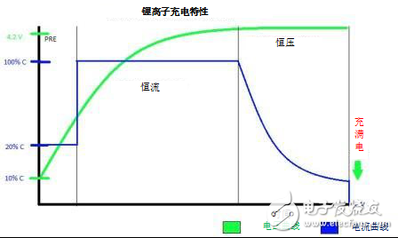
Figure 1: Typical Li-Ion Battery Charging Curve
The latter paragraph describes a typical charging scheme with few handshaking and normal charging rates. The latest method is to maximize the charging time by providing more energy to the battery during the CC phase. These methods use proprietary charging algorithms or use mainstream standards such as the USB Powered Programmable Power Supply (PPS) standard. Wall chargers and devices are capable of continuous handshake, intelligently communicating battery requirements and maximizing charging efficiency.
The two main fast charging methods are high voltage and low current (conventional methods), high current and low voltage (new mainstream trend). The first method uses an existing charging line and limits the current to approximately 2A while raising the voltage to 15V. The problem with this method is that the heat dissipation during the voltage-switching phase of the device is high, resulting in a shortened battery life and a reduction in the maximum allowable energy that can be transferred to the battery.
The second method uses a voltage close to the battery voltage and a higher current that can flow directly to the battery. This method is often referred to as direct charge or flash charge. This method allows a higher charge rate to be achieved at lower temperatures because there is no voltage conversion on the device side. However, flash charging requires a special charging line to achieve higher current flow. The idea is to try to charge the battery at a rate as close as possible to the maximum allowed rate to minimize charging time.
Consider the flasher temperature profile of the flash; it is becoming more popular and is used by most existing standards. Figure 2 shows a high-level block diagram of a flash charging system.
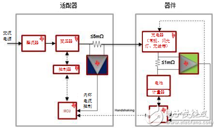
Figure 2: High-level block diagram of the flash charging solution
As shown in Figure 2, an accurate current control loop is necessary to achieve faster charging times and an additional layer of protection on top of other modules (battery chargers and fuel gauges have used similar modules). Although you can integrate current sensing, it is difficult to match the level of accuracy required to achieve a dedicated current-sense solution using a small shunt resistor to minimize heat dissipation, and it is difficult to match the ability to monitor high-side currents.
TI offers a variety of dedicated current sensors for flash charging. These solutions include the INA210 series, which offers excellent accuracy over a wide dynamic range; the INA199 has an excellent combination of precision and cost; and the new INA181 series offers the best value in terms of bandwidth, accuracy and price. In this application, the INA181's wide 350kHz closed-loop bandwidth enables the detection of fast ripples in the CC signal – for battery protection and safety, it contains information that can be used to maximize CC and minimize protection achieve.
Figure 3 shows a typical flash signal seen from the output of a wall charger.
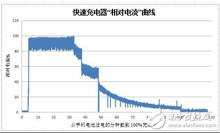
Figure 3: Example of a flash charge flow curve
In summary, the main limitation of today's fast charging methods is that heat is close to the battery, which limits the maximum allowable energy that can be delivered, thereby limiting the charging time to a minimum. In addition, high temperatures have concerns about safety issues and reduced battery life. Flash charging has great potential because it allows for high levels of energy transfer at relatively cold temperatures while maximizing charging efficiency and minimizing charging time. Achieving this high efficiency requires an accurate current control loop, which is better achieved with a dedicated current sensor.
other information· Learn more about TI's portfolio of current sense amplifiers.
· Start using the current sense amplifier video training series.
· Read these TI technical notes:
· "Current mode control in switching power supplies".
· “External Current Sense Amplifiers for Current Sensing and Integrated On-Board Amplifiersâ€.
Landscape brightening,Landscape lighting,Led landscape lighting
Kindwin Technology (H.K.) Limited , https://www.ktlleds.com