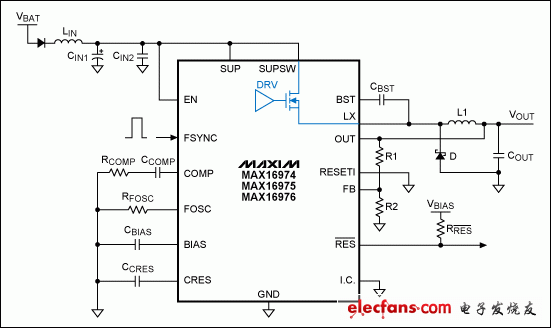
The MAX16974/MAX16975/MAX16976 converters are standard buck controllers designed for automotive applications. These controllers operate through an internal high-side N-channel FET and an external freewheeling diode. A reasonable PCB (printed circuit board) layout, combined with appropriate external components, is critical to the reliable operation of the system and to minimize EMI emissions. The circuit shown in Figure 1 shows a typical application circuit for these high performance converters.
Typical application circuit

Figure 1. Typical application circuit
DC and AC current paths
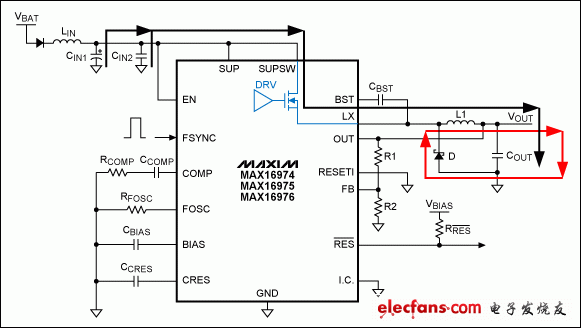
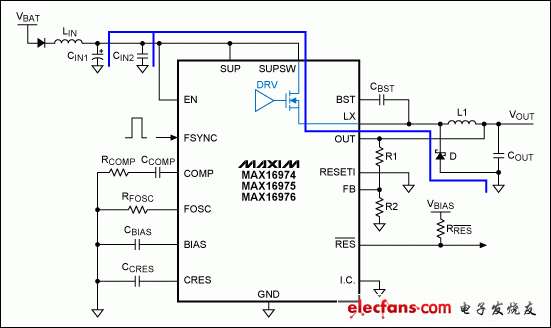
Figure 2 shows the AC and DC current paths for the MAX16974/MAX16975/MAX16976 series.

Figure 2a. DC current path with HSFET turned on (black) or freewheeling diode turned on (red)

Figure 2b. AC branch of the DC current path shown in Figure 2a
Dongguan Yijia Optoelectronics Co., Ltd. , https://www.everbestlcdlcm.com