Abstract: In the energy-saving control of central air-conditioning systems, each sensor is connected to the corresponding input of the automatic control device via a numbered standard interface. In order to avoid failures due to operational errors during use, we have developed an automatic sensor identification device that automatically identifies the type and purpose of each sensor and ensures that the automatic control unit always operates in accordance with the agreed input-output relationship.
0 Preface
Building energy conservation is an emerging field that is rushing into research and investment at home and abroad. Central air conditioning is one of the most important equipments for modern buildings. Central air conditioning provides a comfortable environment and brings huge energy consumption. . According to statistics, in large and medium-sized hotels and hotels, the energy consumed by central air-conditioning accounts for more than 60% of the building's energy consumption. Therefore, the development and application of central air-conditioning energy-saving technology is an important area for building energy conservation, and it is actively developed and reasonable. The use of energy-saving control technology is the fundamental way to reduce energy consumption in air-conditioning. In the central air-conditioning energy-saving system, the temperature is detected by sensors installed on the outlet pipe and the return pipe, and the actual temperature is sent to the automatic control device for comparison with the set temperature and operation control. This paper mainly introduces the application of automatic sensor identification device in central air conditioning energy saving control.
1 Central air conditioning variable flow energy saving principle
Variable flow refers to the flow of a fluid (gas or liquid) in a particular pipe or duct, the flow rate of which varies according to a specific law. The purpose of using variable flow to transport fluids is to achieve energy savings in the delivery system while meeting the end load requirements. The central air conditioning system is mainly composed of air conditioning main engine, cold and warm water control equipment, cooling water control equipment and cooling tower fan control equipment. In the central air conditioning system, the capacity of the cold temperature water pump, the cooling water pump and the cooling tower fan is according to the maximum design heat load of the building. Selected, with a margin of 10% to 15%, the system operates at a fixed maximum water flow for a long time throughout the year.
Due to seasonal, day and night and user load changes, the actual thermal load of the air conditioner is much lower than the design load for most of the time. The operating hours with a load rate below 50% in a year account for more than 50% of the total operating time. When the air conditioning cooling load changes, the required air conditioning circulating water volume should also change with the load. Therefore, the variable flow control technology can realize the energy saving of the central air conditioning system, including the variable flow control of the central air conditioning primary pump system for the cold temperature water pump, the cooling water pump and the cooling tower fan; the fresh air system, the variable air volume system, and the primary air conditioning system Variable flow control such as wind system and secondary return air system. These variable flow control systems generally use automatic control technology and variable frequency speed control technology to achieve energy saving by controlling flow.
After the system is started normally, the detected data is transmitted to the intelligent I/O module by the temperature sensor and transmitter, flow sensor and transmitter, differential pressure sensor and transmitter, smart meter, etc. installed on site, and the measured value is Comparing the set values, calculating the deviation of the magnitude and the rate of change of the deviation, and adjusting the operating frequency of the inverter in real time through the fuzzy control operation to meet the needs of the system load. The detected cold water return water temperature is used to control the temperature of the cold water pump; the detected cooling water outlet temperature is used to control the cooling water pump speed; and the detected cooling water inlet water temperature is used to control the cooling tower fan speed. When the water pump and the fan are running, the power consumption is proportional to the cube of the speed. The speed can be controlled to achieve a large energy saving. The differential pressure of the return water main pipe detected by the differential pressure sensor is mainly used for the protection function. When the pressure difference exceeds a certain amount, the opening degree of the bypass valve is controlled to ensure the safe operation of the system; the value of the smart meter detection is used for the system. Manage, calculate the energy consumed by the system, and draw a history of energy saving curves and energy savings.
2 sensor automatic identification device composition
Air-conditioning mainframes are usually installed in the basement or in special rooms. The working environment is harsh and far away from the room where heating (or cooling) is required. During the operation of the air-conditioning, we need to supply the return water temperature and cooling water into and out of the chilled water. The temperature is collected. In the traditional air conditioning system, the sensor and the control computer are connected by cable connection. When debugging, monitoring and overhauling the system, it is often necessary to disconnect the connection cable of the sensor output for some tests. Operation, when the operation is completed, the connection error is likely to occur when the connection is restored. At the engineering site, when the sensor number identification is ambiguous or even the identification disappears, the engineering technical documents are difficult to obtain even lost. In this way, considerable manpower, material resources and time must be spent to identify and confirm the connection relationship between each sensor and each input. Once the connection between the sensor and the input port is wrong, the system will malfunction. In response to this situation, we study a sensor automatic identification device, which uses the automatic sensor identification technology to automatically identify the types and uses of each sensor online, without manual number identification and checkpoint connection, which can ensure that the system automatically inputs according to the design convention. - Output relationship operation can reduce system construction, commissioning, maintenance costs, and avoid unexpected failures caused by connection errors. This is a device that automatically recognizes the type and purpose of each sensor without the use of an interface number, and ensures that the automatic control device always operates in accordance with the agreed input-output relationship.
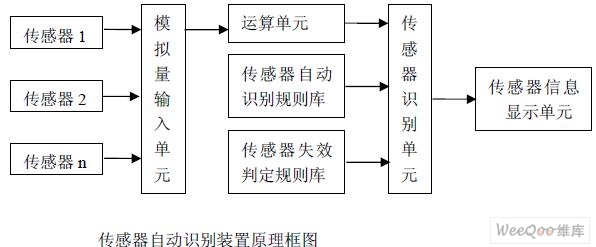
The sensor automatic identification device is composed of a sensor, an analog input unit, an arithmetic unit, a sensor automatic identification rule base, a sensor failure judgment rule base, a sensor recognition unit, and a sensor information display unit. The principle block diagram is as follows:
(1) The number of sensors is 1 to 10, and the analog levels output by each sensor are the same. The actual effective range of physical quantities collected by each sensor is smaller than the full scale range or the characteristic quantity of physical quantities collected by each sensor. For example, the time domain, frequency domain or correlation feature quantity has obvious differences. The sensor group in most commonly used automatic devices can meet the requirements.
(2) The arithmetic unit performs a feature quantity extraction operation on each sensor output signal, and the extracted feature quantity may have an arithmetic mean value, a variance, a range difference, a difference value, a fluctuation period, and the like. The number of arithmetic samples can be 10 to 20. The feature quantity and number of samples that need to be extracted during operation are determined by the automatic recognition rule base.
(3) The automatic identification rule base and the failure judgment rule base are preset offline according to the type and characteristics of the sensors used in the system. The rules built in the two rule bases come from professional knowledge, common sense knowledge and experience knowledge.
(4) The identification unit automatically recognizes each sensor feature quantity output by the operation unit according to the rules of the automatic identification rule base and the failure determination rule base, and the identification unit outputs the type, use, and position of the detection point for the system. And whether it is absolutely invalid. The output of the identification unit is sent to the computer controller in the form of a digital signal. The controller confirms that each sensor is normal and then enters the control operation program, and ensures that the control operation is performed according to the design-input-output relationship and is displayed on the display.
(5) The automatic identification and failure determination procedure is executed after the central air conditioning system is operated for 15 minutes.
3 sensor automatic identification device works
(1) Collect the sampling values ​​of each sensor, the number of samples is 10 to 20 times, and the sampling period is 0.5 to 5S.
(2) The sampled values ​​of the sensor are respectively subjected to the feature quantity extraction operation by the operation unit, and the extracted feature quantities have arithmetic mean, variance, range of variation, derivative of data, time, 1, 2, 3, 4, and data fluctuation period. , frequency domain characteristics, correlation. The number and type of feature quantities that need to be extracted differ depending on the automatic control device, and are determined by the built-in automatic identification rule base.
(3) The feature quantity of each sensor is compared and judged by the sensor identification unit. The input information of the comparison judgment operation is the feature quantity, type and use of each sensor; the basis of the comparison judgment operation is the automatic identification rule base of the sensor; the decision of the comparison judgment operation is the type, use and automatic control device of each sensor. Input port.
(4) After the automatic control device is in normal operation, long-term online monitoring of the data collected by each sensor is performed. When the data collected by the sensor deviates from the range, it is judged as absolute failure, and the sensor information display unit provides an alarm signal; if the data collected by the sensor is within the range but deviates from the normal range, it is judged as relative failure (relative failure occurs after system startup) It has not yet entered the initial stage of stable operation. It provides the keep-alive signal (the hold time T can be set). After the hold time T, the data collected by the sensor is within the range of the range but still deviates from the normal range. It is judged that the connection relationship is wrong and the sensor information is displayed. The unit provides a connection error alarm signal. The basis for long-term monitoring is the library of failure identification rules.
The hardware and software for realizing this automatic identification method mainly involve a CPU unit, a memory, and an operation interface. The configuration of hardware and software can be considered together in the hardware and software configuration of the automatic control device, and it is not necessary to set it alone.
4 Conclusion
The key to the automatic sensor identification device is to correctly establish the sensor automatic identification rule base and the sensor failure determination rule base. In addition, the sensor operation unit should also establish various calculation rules. We can select the operation results of different operation models to obtain optimal control of the controlled system. The device is different from the method of additionally adding a wired or wireless channel, and encoding and identifying the sensor, but using the feature quantity of the signal transmitted by the sensor itself, that is, the method of replacing the hardware configuration with software technology. The device can avoid the wrong connection relationship between the sensor and the control device, and ensure that the automatic control device always operates according to the agreed input-output relationship, thereby reducing construction and debugging costs and improving work efficiency. The sensor automatic identification device is used in the central air conditioning energy saving system. This technology can also be used in other motor drag automatic control systems.
The author of this paper innovates: The automatic sensor identification technology is used in the central air-conditioning system to automatically identify the types and uses of each sensor online, ensuring that the system automatically operates in accordance with the design-defined input-output relationship.
:
High Speed Blender,Ipl Laser Hair Removal,Diy Laser Hair Removal,Best Ipl Hair Removal,Epilator Ipl
SHENZHEN CHONDEKUAI TECHNOLOGY CO.LTD , https://www.szfourinone.com